32
Ch 1 Rin, Pin 2 (Brown)
Ch 2 Rin, Pin 3 (Orange)
Ch 3 Rin, Pin 4 (Yellow)
Ch 4 Rin, Pin 5 (Green)
Ch 1 Rin, Pin 6 (Brown)
Ch 2 Rin, Pin 7 (Orange)
Ch 3 Rin, Pin 8 (Yellow)
Ch 4 Rin, Pin 9 (Green)
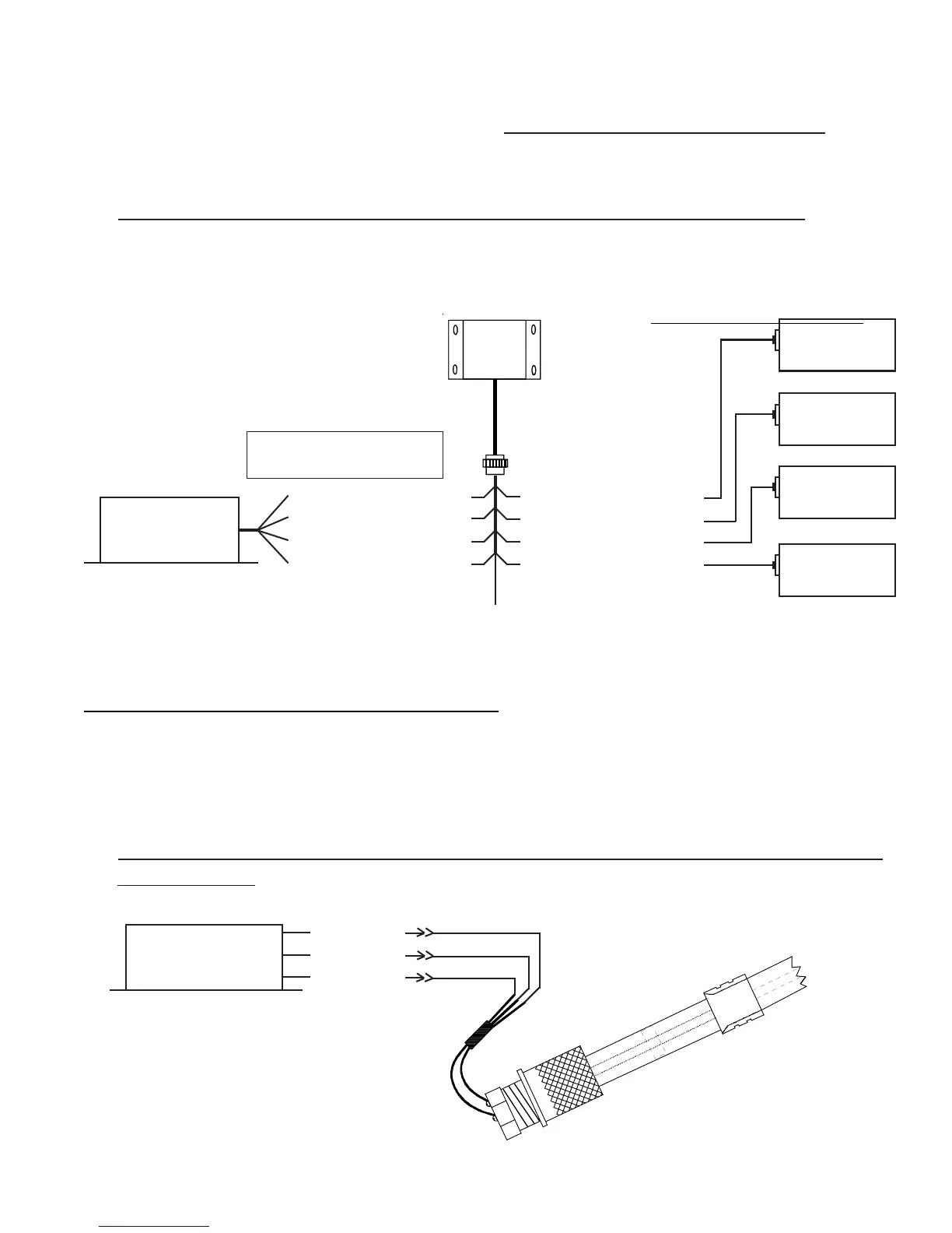
EDC
Resistive Input
(1 of 4)
+Vin, Pin 1, (Red)
To Bus (via CGR/EDC Circuit Breaker)
Fuel Tank
1
Fuel Tank
2
Fuel Tank
3
Fuel Tank
4
RFLM-4-12V (for a 12Volt system)
RFLM-4-24V (for a 24Volt system)
Bottom Connector
Connect only the wires for
which you have Fuel Tanks.
+5V (Red)
Gnd (Black)
Cin (White)
P-300C Capacitive
Fuel Level Probe
EDC
Capacitive Input
(1 of 4)
Bottom Connector
tion) and connect to the fuel flow transducer. When connecting to the Fuel Flow Transducer, leave some
slack in the cable exiting the transducer to prevent future damage to the transducer.
If the flow tranducer is hard mounted to a bracket,
DO NOT connect the Black Gound WireDO NOT connect the Black Gound Wire
DO NOT connect the Black Gound WireDO NOT connect the Black Gound Wire
DO NOT connect the Black Gound Wire
on the
flow transducer. The bracket will provide the necessary ground to the transducer.
3.6 Connect the EDC Harness to the Existing Capacitive Fuel Level System:
The output signal of a capacitive fuel level system (on a certified aircraft) will have a wire connected from
the capacitive system to the fuel level gauge. The signal on this wire will be 0 to approx 150mV DC. The
other side of the gauge will be grounded. Re-route the signal wire (currently connected to the fuel level
gauge) to one of the resistive inputs on the bottom connector of the EDC.
DO NOT connect an RFLM
unit into this system, damage to the system may occur. The current fuel level gauge must be remove from
the system.
A 332-ohm resistor should be connected from the signal wire to ground. For a CGR-30 STC’d system,
this resistor is integrated into the wire harness supplied with the system.
3.7 Connect the RFLM-4-x Harness to the EDC Connector and to the Resistive Fuel
Level Sensors:
DO NOT connect the RFLM into a capacitive system, damage may occur. Route the appropriate resistive