2.13 Install the Voice Alarm Control Panel (OEM Only):
If the voice alarms provided by the CGR are to be used, the AV-17CP Control Panel will need to be
installed in the aircraft instrument panel.
A. Locate the Control Panel and Switch in the
AV-17CP packet. Find an appropriate mounting
location on the aircraft instrument panel for the
Control Panel and Switch. The Switch will require
a 3/4" clearance behind the aircraft instrument
panel.
B. Using the AV-17CP Control Panel as a template,
mark the aircraft instrument panel and drill a 1/
4" hole for the AV-17CP Switch.
C. Mount the Switch from behind the aircraft instru-
ment panel. Be careful not to damage the
silkscreening on the Control Panel. The Switch must be mounted with the
white/orange wirewhite/orange wire
white/orange wirewhite/orange wire
white/orange wire
upup
upup
up
..
..
. The lock washer should be mounted on the Switch and behind the aircraft instrument panel.
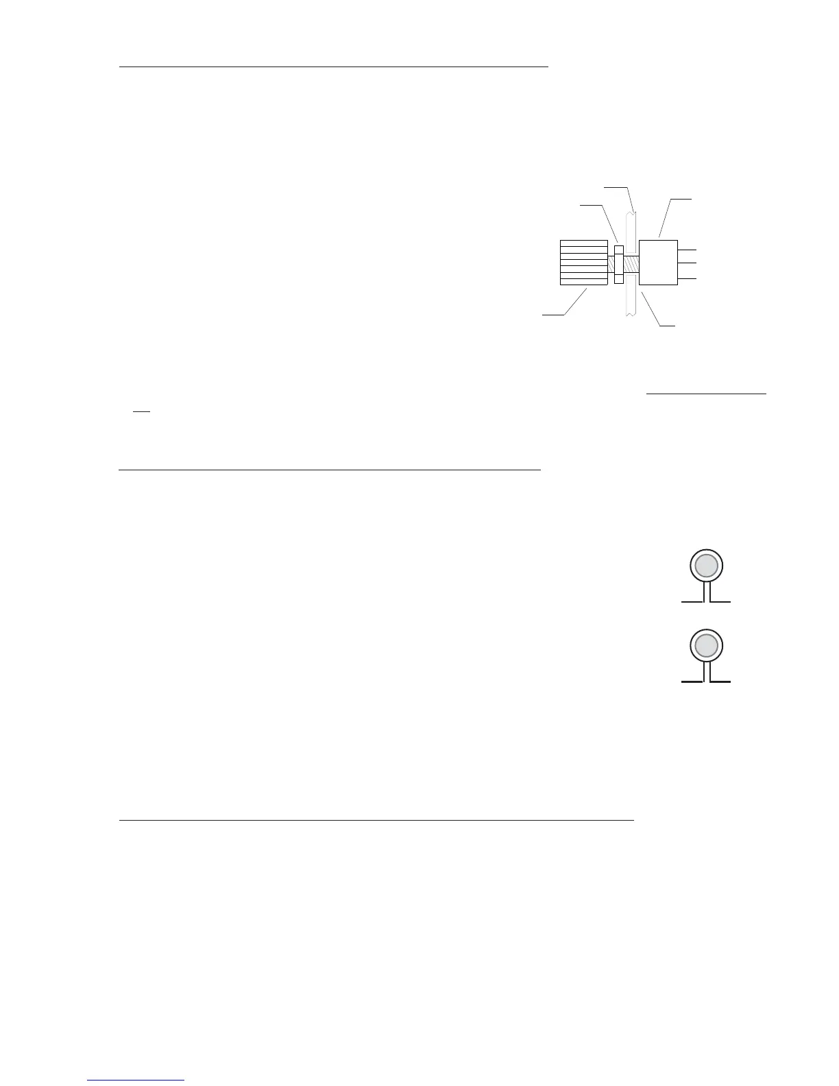
2.14 Install the Intensity Control Pot CP-1A (Optional):
The backlight display intensity of the CGR is controlled by an external source. The input voltage levels
for a bright and dim setting on the CGR-30 are programmable. Your existing reostat can provide this
signal or you may purchase the CP-1A.
The CP-1A Intensity Control Pot will provide the proper voltage for one or
many CGR-30 units and for the external Master Warning and Caution lights
associated with each instrument. To install the CP-1A perform the following:
A. Find an appropriate mounting location on the aircraft instrument
panel for the CP-1A Control Pot. The Pot will require a 2" clearance
behind the aircraft instrument panel.
B. Mark the aircraft instrument panel and drill a 1/4" hole for the Pot.
C. Mount the Pot from behind the aircraft instrument panel and install the knob.
2.15 Install the Master Warning (red) and Caution (yellow) Lights:
Install the Warning and Caution Lights within the pilot’s primary field of view.
A. Locate the Red (AL-1R), Yellow (AL-1Y) lights and the Mounting Plate in the kit. Find an appro-
priate mounting location within 12" of the pilot's visual centerline. The lights will require 3/4"
clearance behind the aircraft instrument panel.
B. If the aircraft currently has Caution and Warning Lights for an existing CGR-30P or you are
installing the CGR-30C and a CGR-30P, install the Mounting Plates as follows:
25
Nut
Pot
1/4" Hole
Knob
Aircraft Instrument
Panel
To CGR
(Wht/Orng)
CP-1A
To CGR
(Yellow)
To CGR
(Red)