24
- Water logged floats.
If you find inconsistent or inaccurate fuel level readings (due to a
defective resistive fuel level sender), you must have the sender
replaced. Inaccurate readings can lead to a dangerous situation.
The CGR-30 depends on the fuel level sender for accurate fuel level
information. Read the “Important Notice” in the CGR Operating
Instructions.
The P-300M is a float type fuel level sender that uses a magnet and
pickup device to detect the float position and produce the signal for
the CGR-30 system. The P-300M has no wiper or resistive element
and there is no tension on the bearing surfaces. It is not subject to
the many problems associated with resistive type senders. The P-
300M has nothing to wear out or affect inaccurate fuel level read-
ings. Also, the P-300M does not require electricity to flow through
an element and wiper saturated in fuel, as is the case with resistive
senders.
2.12 Install the Resistive Fuel Level Module (RFLM-
4-X):
The RFLM-4 is a Resistive Fuel Level Module that provides pull-up resistors for 4 resistive fuel level
sensors. This module is required to interface an EDC Resistive Fuel Level Input to a Resistive Fuel
Sensor.
Warring:Warring:
Warring:Warring:
Warring: DO NOT connect an RFLM-4 to the output of an existing aircraft’s Capacitive System,
damage to the system may occur. The small output voltage of an existing capacitive system currently
drives a fuel level gauge. This output wire should be routed to one of the resistive fuel level inputs on the
EDC with NO connection to an RFLM unit.
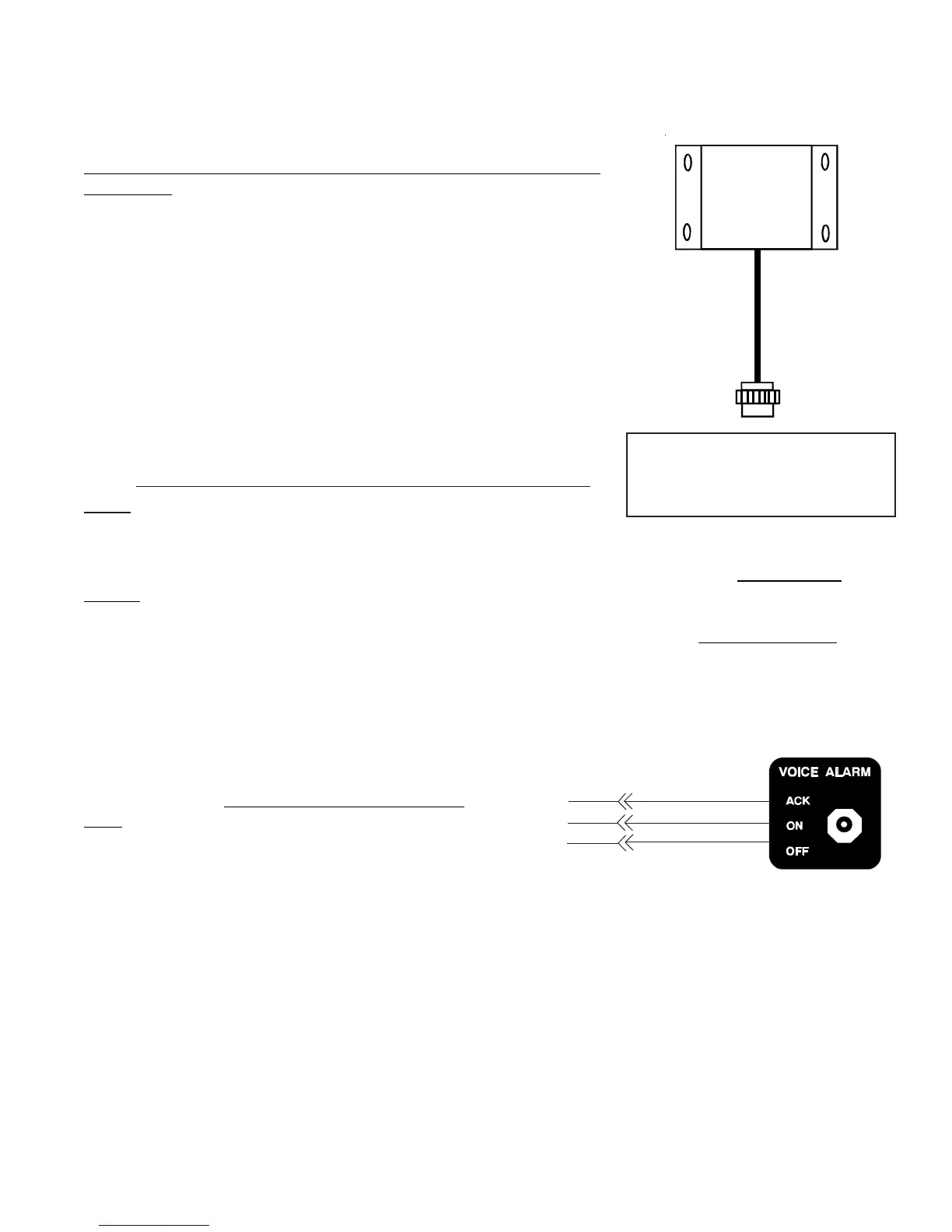
There are two RFLM-4 modules available. The
RFLM-4-12V operates on a 12-volt electrical
system and the RFLM-4-24V operates on a 24-volt
electrical system. The appropriate model must be
used.
Mount the RFLM-4-X to the inside firewall or to
an equipment bay under the aircraft instrument panel. Use the holes in the bot-
tom plate to mount the unit. Only two mounting holes are required.
Note: For each Fuel Level Channel on the EDC you can use either the Resistive Input or the Capacitive
Input, but not both.
To EDC Resistive Fuel
Level Inputs (Bottom Connector)
and the Fuel Level Sensor.
AV-17CP, Control Panel
White/Brown
White/Red
White/Orange
(OFF)
(ACK)
(+5V)
To CGR