fuel level input wires (for the number of tanks to be monitored) in the RFLM-4-x harness to the EDC
Bottom Connector. Plug the wires into the appropriate resistive fuel level channels. The excessive wire
can be cut and spliced, bundled and tie wrapped up or cut to length and new D-Sub pin installed (see the
“Working with Connectors” section of this manual for more information). Route and connect the corre-
sponding wires in the RFLM-4-x wire harness to the appropriate fuel tank sensors. Route the red wire (in
pin 1 of the RFLM-4-x connector) to the aircraft bus via the CGR/EDC 5-amp circuit breaker.
33
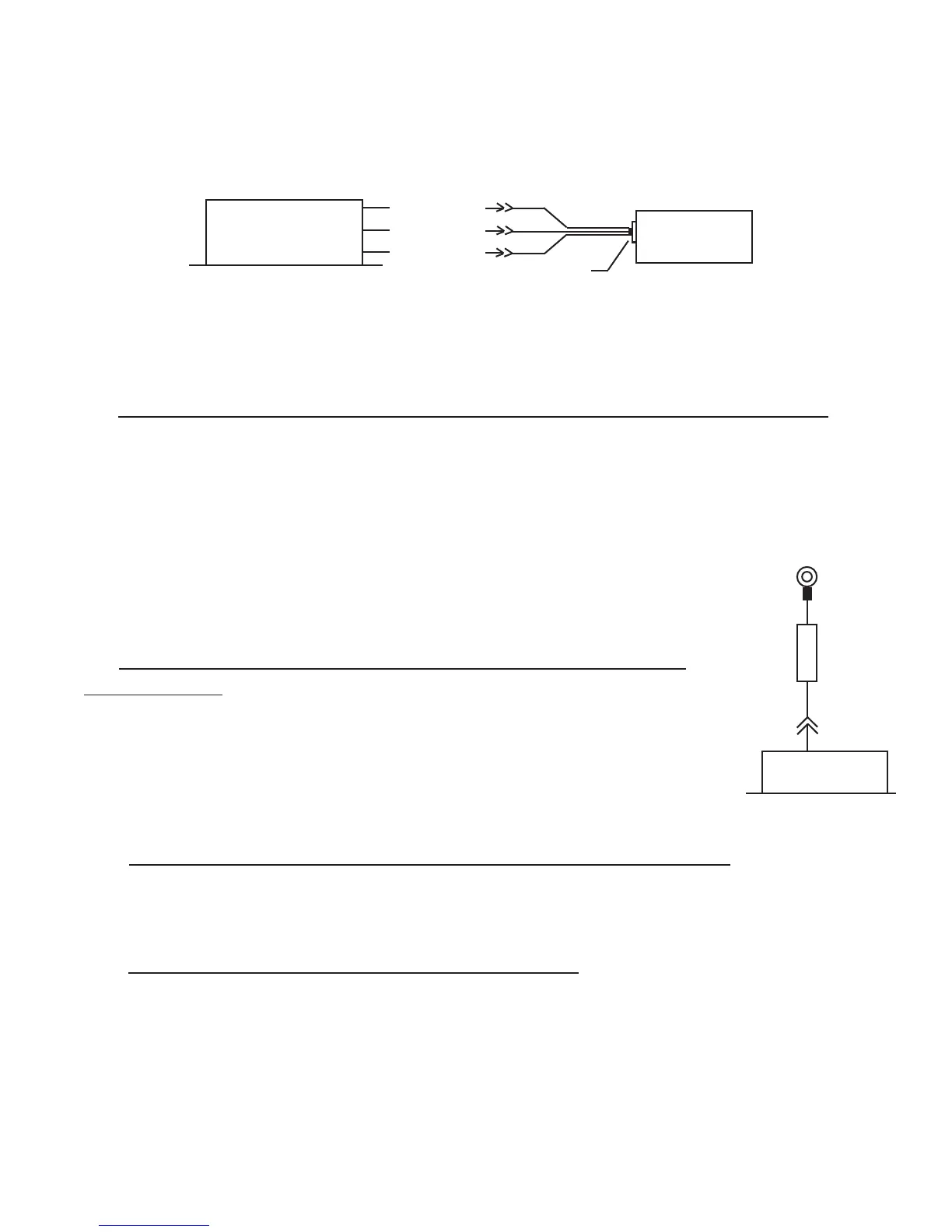
To P-lead
EDC
RPM Input
(1 of 2)
Ring
Terminal
Isolator
(1 of 2)
Bottom Connector
Fuel Tank
1
+5V (Red)
Gnd (Black)
Rin (White)
EDC
Resistive Input
(1 of 4)
Bottom Connector
P-300M
Fuel Level Sensor
.
.
Total of 4 Fuel
Tanks
3.8 Connect the EDC Harness to the EI P-300C Capacitive Fuel Level Probes:
Route the appropriate capacitive fuel level wires (for the number of tanks to be monitored) in the EDC
harnesses to the capacitive fuel level probes. Cut the wires to length, install the appropriate connectors
(see the “Working with Connectors” section of this manual for more information) and connect to the
capacitive fuel level probe.
Note: The capacitive fuel level channels are shared with the resistive channels.
A single capacitive
and resistive channel cannot be used simultaneously.
3.9 Connect the EDC Harness to the EI P-300M Magnetic Fuel
Level Senders:
Route the appropriate fuel level wires (for the number of tanks to be monitored) in
the EDC harnesses to the
P-300M magnetic fuel level senders. Cut the wires to length, install the appropriate
conntectors and connect to the P-300M fuel level sender.
3.10 Connect the EDC Harness (Volts Measurement Pin) to the Bus:
Pin 35 of the EDC top connector monitors bus voltage. Connect this pin to the bus to be monitored.
3.11 Connect the EDC Harness to the RPM Signals:
If the EDC RPM Ch 1 and Ch 2 Inputs are to be connected to a Magneto, Ignition Coil or CDI Ignition