51
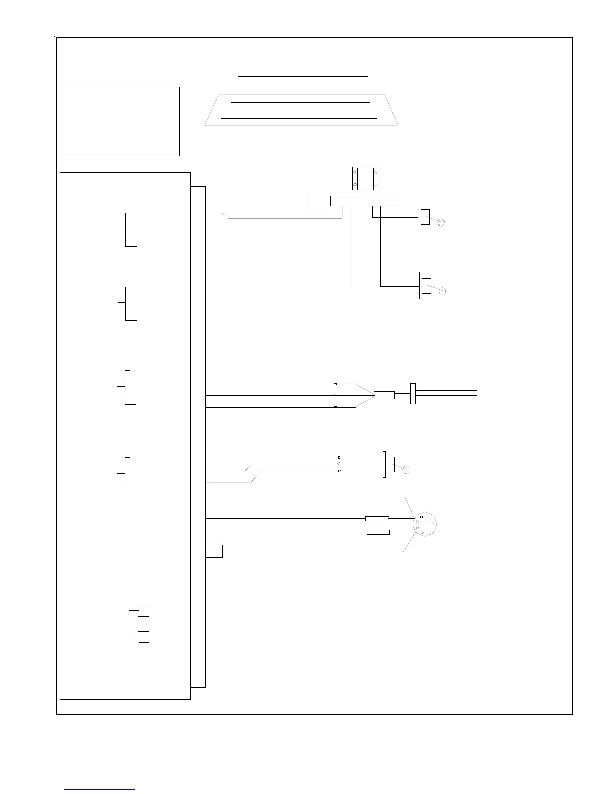
EDC Work Sheet
Bottom Connector
21
22
EDC-33P
DB-37
EDC-33P-4/6
37
19
20
1
Extra Gnd
*1 Unused Pressure Channel
Inputs Must Be Grounded.
Electronics International inc.
Notes:
DB-37 Back View, Wire Side
23
Resistive Input
20
Extra Gnd
Extra Gnd
Extra Gnd
Extra Gnd
+5V
Fuel Level Ch1
Gnd
Capacitive In
33
34
35
Resistive Input
32
+5V
Fuel Level Ch3
Gnd
Capacitive In
2
3
4Resistive Input
1
+5V
Fuel Level Ch2
Gnd
Capacitive In
15
16
17
Resistive Input
+5V
Fuel Level Ch4
Gnd
Capacitive In
14
26
25
RPM Ch1
RPM Ch2
5
7
18
19
24
27
28
36
37
Extra Gnd
for shelds.
-- Extra Gnds maybe used
Extra Gnd
Short Pin 27 to 28 for 6-Cyl
RFLM-4-24
123456789
CGR Breaker
To Bus via
Ch1
Ch1
Ch2
Ch2
Existing
Resistive Float
Existing
Resistive Float
L Main
R Main
Resistive Float Interface
P-300M
Magnetic Sensor
R Aux
P-300C
Capacitance Probe
IMC
L Aux
Red
Blk
Wht
may be used for annunciators.
-- Unused Res Fuel Level Ch's
Open for 4-Cyl
+ In (Yel)
12
30
- In (Red)
Temp Ch 16
+ In (Yel)
13
31
- In (Red)
Temp Ch 17
Extra +5V
6
Extra +5V
8
Extra Gnd
9
Extra +5V
10
Extra Gnd
11
Extra Gnd
29
Mag Switch
Left Mag
Right Mag
Isolator
P-Lead (to left mag)
P-Lead (to right mag)
Isolator
Wht/Brn
Wht/Org
3'
Red
Blk
Wht
Aircraft ID:
SAMPLE
DB-37 (421-0337-00)
Pin (421-0301-00)
DB-9M Connector (421-0343-00)
Pin (421-0301-00)