4 Advanced System Operation
iConnect
Installation Manual
26
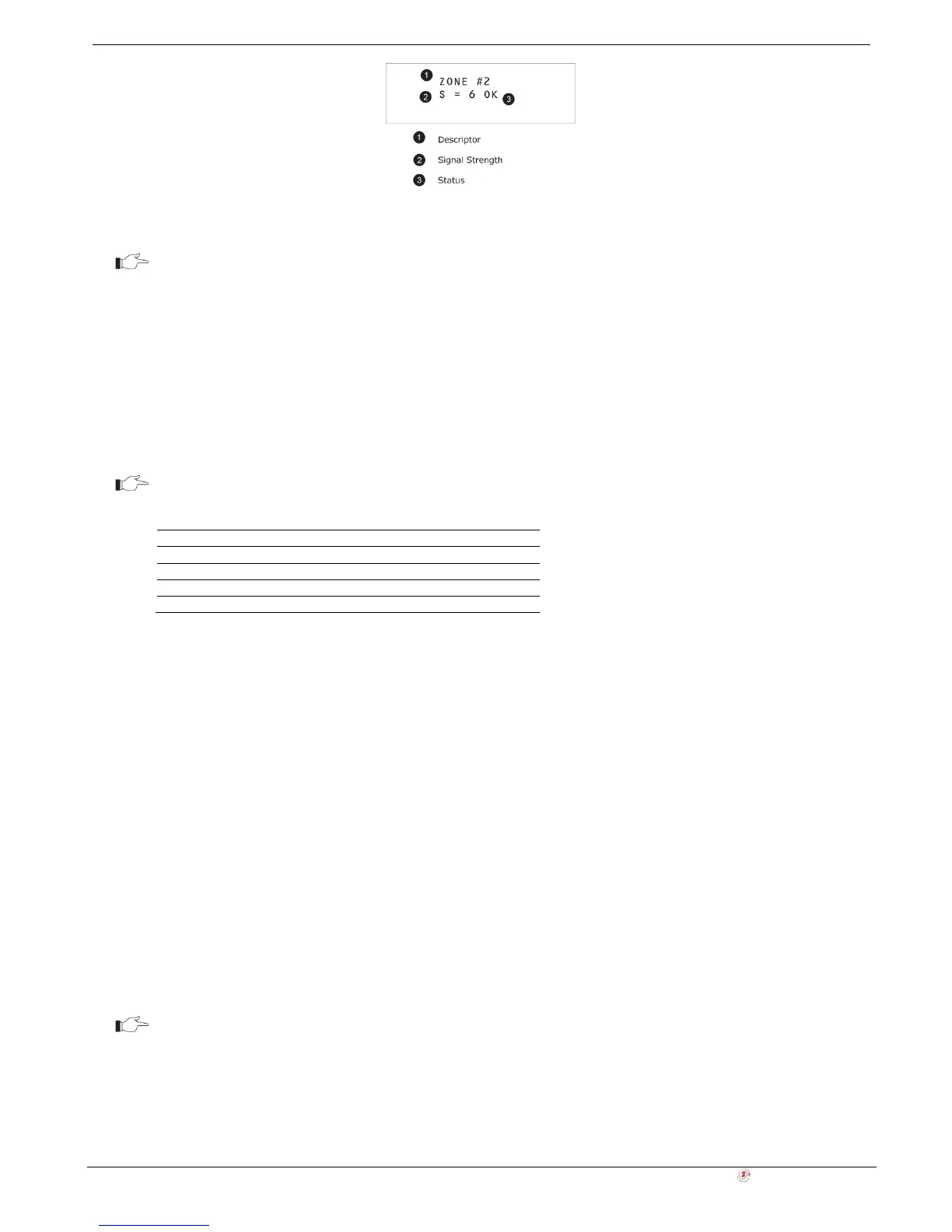
Figure 4-3: TX List Display
In most cases, an "out of synchronization" condition indicates that an unauthorized attempt
at grabbing the transmission has occurred – i.e. a previous transmission has been recorded
and sent by somebody trying to violate the system.
TX Test
TX Test enables you to identify transmitters and test their signal strength. In TX Test mode, each time a transmission is
received, the activated transmitter is displayed. If you enter this function using the Master code, a chime is sounded
every time a transmission is received. If you enter this function using the Installer code, a sequence of tones in
combination with subsequent LED flashes indicate the transmitter’s signal strength – see Table 4-2.
This feature helps you to determine the best location to install a transmitter.
The lowest recommended signal strength for any installed transmitter is 2. If the received
signal strength is lower than 2, relocate the transmitter.
Table 4-2: Signal Strength Tones
Signal Strength Tones LED Flash
1 1 Tone 1
2 2 Tones 2
3 3 Tones 3
4 4 Tones 4
To initiate TX Test mode:
1. From the Service menu, select Transmitters, TX Test [7042].
2. Activate a transmitter; the transmitter’s details are displayed.
3. When you have finished, press Χ to exit TX Test mode.
RF Link Test
RF Link Test enables you to measure the RF noise levels between a selected transmitter and the system’s receiver.
To view RF Link level reading:
1. From the Service menu, select RF Link Test [7043]; the first transmitter on the list is displayed.
2. Using the arrow buttons, scroll through the list and select a transmitter.
3. Press '√ʹ and activate the selected transmitter, e.g. press keyfob button. The RF noise levels of the selected
transmitter and the system's receiver are displayed.
4. When you have finished, press Χ to exit RF Link Test mode.
Environmental RSSI
Environmental RSSI Test enables you to measure the RF noise level of the systems environment. The Control System
will start measuring the RSSI level every second, and it will display the result on the LCD.
RSSI level can jump momentarily when a detector is activated. It doesn’t mean that the
receiver is noisy.
To view the Environment RSSI level reading:
1. From the Service menu, select ENV. RSSI [7044]; the RF noise of the system's environment is displayed.
2. When you have finished, press Χ to exit the Environmental RSSI Test mode.