13
ENGLISH
devices or slightly damaged parts must
be inspected for proper functioning as
specified. Check to see that all moving
parts work properly and do not jam. All
parts must be correctly installed and
meet all conditions necessary for the
proper operation of the electric tool.
Damaged protection devices or parts
must be repaired or replaced by a quali-
fied specialist. Have damaged switches
replaced by a service centre. Do not
operate electric tool if the switch can not
be turned ON or OFF.
Keep handles free of oil and grease.
3.3 Symbols used through-
out these instructions
Danger!
Indicates risk of personal
injury or severe material
damage.
Risk of electric shock!
Risk of personal injury by elec-
tric shock.
Drawing-in/trapping hazard!
Risk of personal injury by body
parts or clothing being drawn
into the rotating saw blade.
Caution!
Risk of material damage
Note:
Supplementary information
3.4 Safety devices
Riving knife
The riving knife (13) prevents the work-
piece from being caught by the rising
teeth of the saw blade and being thrown
against the operator.
Always have riving knife installed during
operation.
Blade guard
The blade guard (14) protects against
unintentional contact with the saw blade
and from chips flying about.
Always have blade guard installed dur-
ing operation.
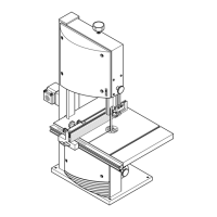
Push stick
The push stick (15) serves as an exten-
sion of the hand and protects against
accidental contact with the saw blade.
Always use push stick if distance
between saw blade and rip fence
(optional accessory) is less than
120 mm.
• Stepless saw blade tilt setting from
90° to 45°.
• Stepless depth of cut setting to
85 mm.
• An undervoltage relay prevents the
machine from starting up when
power is restored after a power fail-
ure.
• All operating elements are located
at the machine’s front.
• Robust sheet metal construction
with galvanized saw table.
• Lower saw blade fully.
• Dismount add-on parts (fence, slid-
ing carriage, table extension).
• If possible use original carton for
shipping.
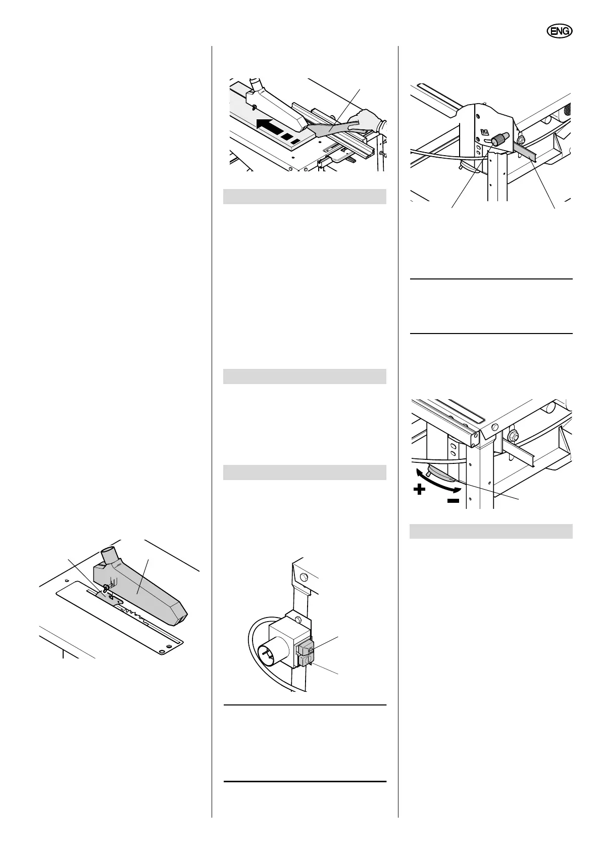
ON/OFF switch with emergency stop
• To start = press green switch button
(17).
• To stop = press red switch button
(16).
Note:
Upon power failure an undervolt-
age relay is activated. This prevents the
starting of the machine when the power
is restored. To restart, the green switch
button must be actuated.
Setting device for saw blade tilt
With the swivel arm (19) the saw blade is
steplessly tilted from 0° to 45°.
In order for the blade angle not to
change during cutting, the blade is
locked in position with the turning knob
(18).
Note:
To utilise the full setting range of
45°, the depth of cut must be reduced
accordingly.
Handwheel for setting the depth of
cut
The depth of cut can be adjusted by
turning the handwheel (20).
Danger!
Modifications of the saw or the
use of parts not tested and approved
by the equipment manufacturer can
lead to unforeseen damage during
operation!
− Assemble the saw in strict accor-
dance with these instructions.
− Use only the parts supplied as
standard delivery.
− Do not change any parts.
− Read instructions for each step
before executing it.
Only if you follow the instructions exactly
does the saw conform to the safety regu-
lations and can be safely operated.
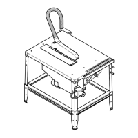
Stand assembly
1. Place table panel upside down on a
stable, level support. To prevent
damage to the table’s surface, place
a cardboard sheet or similar under-
neath.
13 14
4. Special Product Features
5. Transportation
6. Operating Elements
15
16
17
7. Assembly
18
19
20