14
ENGLISH
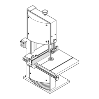
2. Attaching the four leg to the inside of
the table panel’s corners:
− fit hexagon head screws (25) into
holes from the outside;
− from the inside screw on flange
nuts (24) – do not tighten fully
yet.
3. Fit long stanchions (23) between the
side legs, short stanchions (22)
between both front and both rear
legs:
− the wide sides of the stanchions
face the table panel;
− the nibs and recesses must fit
into each other;
− fit hexagon head screws (25)
into holes from the outside;
− from the inside screw on flange
nuts (24) – do not tighten fully
yet.
4. Screwing up the stanchions with
each other:
− Insert hexagon head screws (25);
− screw on flange nuts (24) from
the opposite side.
5. Tighten all screwed connections
6. Push rubber feet (21) on the legs.
7. With the help of a second person
stand the saw on its feet.
Switch enclosure installation
• Attach the switch plate with two
each hexagon head screws (26) and
flange nuts (27) to the left front leg.
The switch buttons must point to the
right-hand side.
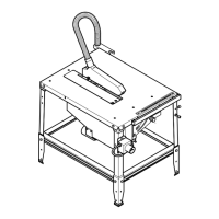
Installation of switch for 110 V 2.2 kW
Motor
1. Loosen both hexagon head screws
(28) on the front edge of the saw
table (at the top of the left leg) with a
13 mm spanner. Take hexagon nuts
and serrated lock washers off the
screws, and remove both screws.
2. Hold switch plate (29) (with attached
ON/OFF switch (30)) to the front
edge of the saw table, lining up the
switchplate holes with the holes in
the table.
Note:
The cable from motor to switch
must not run around the outside of the
leg.
3. Fit a washer on each hexagon head
screw, than fit both screws back into
the holes, through the switch plate
into the table. Secure with serrated
lock washers and hexagon nuts, fin-
gertight only.
4. Before tightening fully, the guide bar
(31) on the left hand side of the saw
table needs to be realigned parallel
with the sawblade.
5. Finally both hexagon head screws
(28) are fully tightened.
Caution!
Pay attention that the cable
does not run over sharp edges and is
not bent.
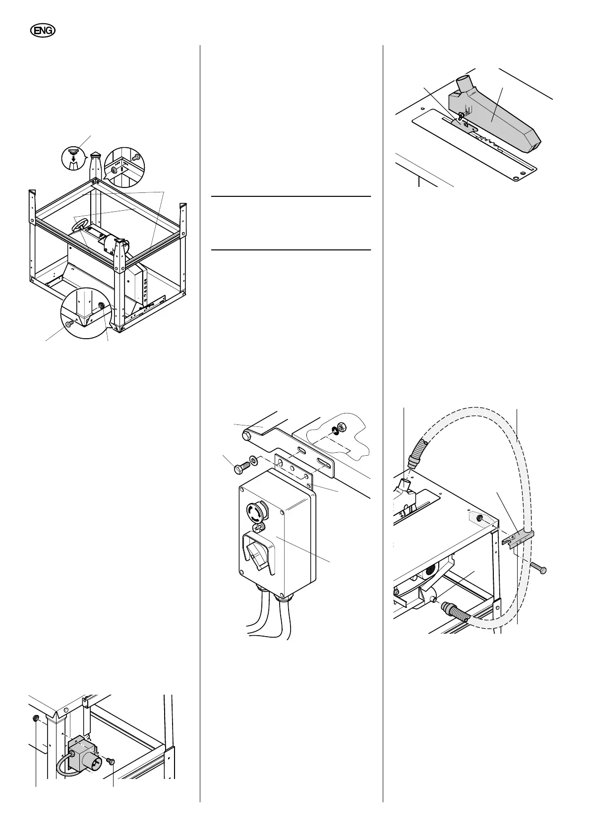
Installing the dust collection gear
1. Install blade guard (33) on riving
knife (32).
The underside of the blade guard
should be in a horizontal position.
2. Push one end of the suction hose
(35) on the blade guard's suction
port (34).
3. Fit other end of the suction hose to
the suction port (37) on the chip-
case.
4. Attach the hose carrier (36), with the
larger opening pointing to the rear,
to the saw table. To do so, loosen
the screws of the right-hand rear leg
and tighten again with the hose car-
rier in position.
5. Hook the suction hose into the hose
carrier.
6. Connect a suitable dust collector to
the dust extraction port on the chip
case assembly.
Tightening the screwed connections
• Check the saw's screwed connec-
tions. Tighten the screwed connec-
tions well hand-tight.
7.1 Mains connection
Danger! Electrical Hazard
Operate saw in dry environ-
ment only.
Operate saw only on a power source
matching the following requirements
(see also "Technical Specifications"):
22
24
23
21
25
2627
29
31
30
28
32 33
34
35
38
37
36