13
5
9
4
8
3
7
2
6
1
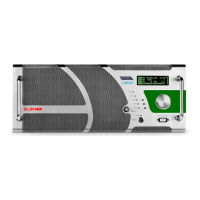
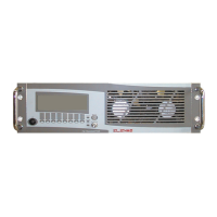
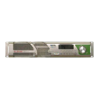
Product description
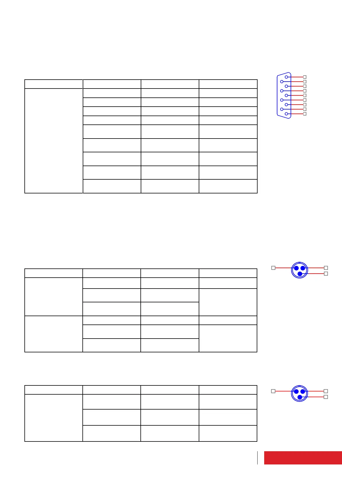
2.1 Description of external connectors
2.1.1 EIA485 connector/Telemetry
N. 6 Front panel (type DB9 - female)
This connector uses Com1, as the connector n. 13 (rear). The two connectors can’t be
used simultaneously.
Connector Pin Meaning Notes
CN3 on board
TG5K2A881
1 Com1 TX+ EIA485/422
2 Com1 TX- EIA485/422
3 Com1 RX+ EIA485/422
4 Com1 RX- EIA485/422
5 Common ground Connected to the
frame
6 Common ground Connected to the
frame
7 Common ground Connected to the
frame
8 Common ground Connected to the
frame
9 Common ground Connected to the
frame
2.1.2 LEFT/RIGHT connectors
N. 5 Rear panel (XLR type - female)
The input impedance is 10 kOhm (default), 600 ohm selectable with jumpers on the
card.
If you have an unbalanced signal, connect the signal at the positive, the common
ground and the negative input to ground (optional if Zin = 10 kOhm, required if Zin =
600 ohms).
Connector Pin Meaning Notes
J01 on board
TG3K1A866 or J1 on
board TG3K2A867
1 Common ground
2 Right channel audio
signal "+"
Differential input
3 Right channel audio
signal "-"
J02 on board
TG3K1A866 or J2 on
board TG3K2A867
1 Common ground
2 Left channel audio
signal "+"
Differential input
3 Left channel audio
signal "-"
2.1.3 AES/EBU connector
N. 6 Rear panel (XLR type - female)
Connector Pin Meaning Notes
J3 on board
TG3K2A867
1 Common ground
2 "Positive" differential
AES-EBU input
3 "Negative" differen-
tial AES-EBU input