CMS200 Product Manual, Issue 6
www.nexo.com Page 11
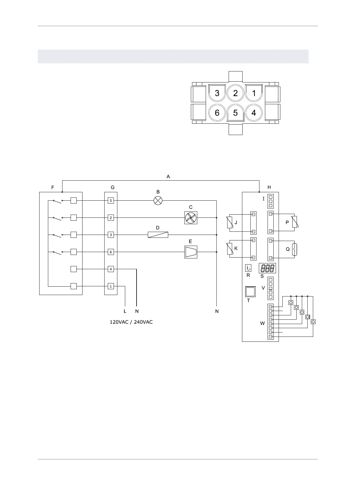
1.2.3 PSM Electrical connections
Pin Description Colour Connectors
1 Live Brown
2 Evaporator fan Yellow
3 Defrost heater Pink
4 Neutral Blue
5 Lights White
6 Compressor Red
1.2.4 Wiring diagram
A - Interface cable H - Control display module Q - Door switch
B - Lights I - RMD R - Motion sensor
C - Evaporator fan J - Evaporator sensor S - Display
D - Defrost heater K - Condenser sensor T - RJ45 Port
E - Compressor L - Live V - Modem interface
F - Power supply module N - Neutral W - Stock / product sensor
G - 6-Way connector P - Appliance sensor