Product Manual, Issue 6 CMS200
www.nexo.comPage 10
The power supply module must be xed using screws with the following characteristics:
` Head
maximum diameter 7.8mm (0.31in) and minimum diameter 6.2mm (0.24in)
` Thread
maximum diameter 4.8mm (0.19in).
The screws must be tightened to a maximum torque of 0.5Nm (0.37lbt).
Note
Using rivets to mount the power supply module invalidates the warranty.
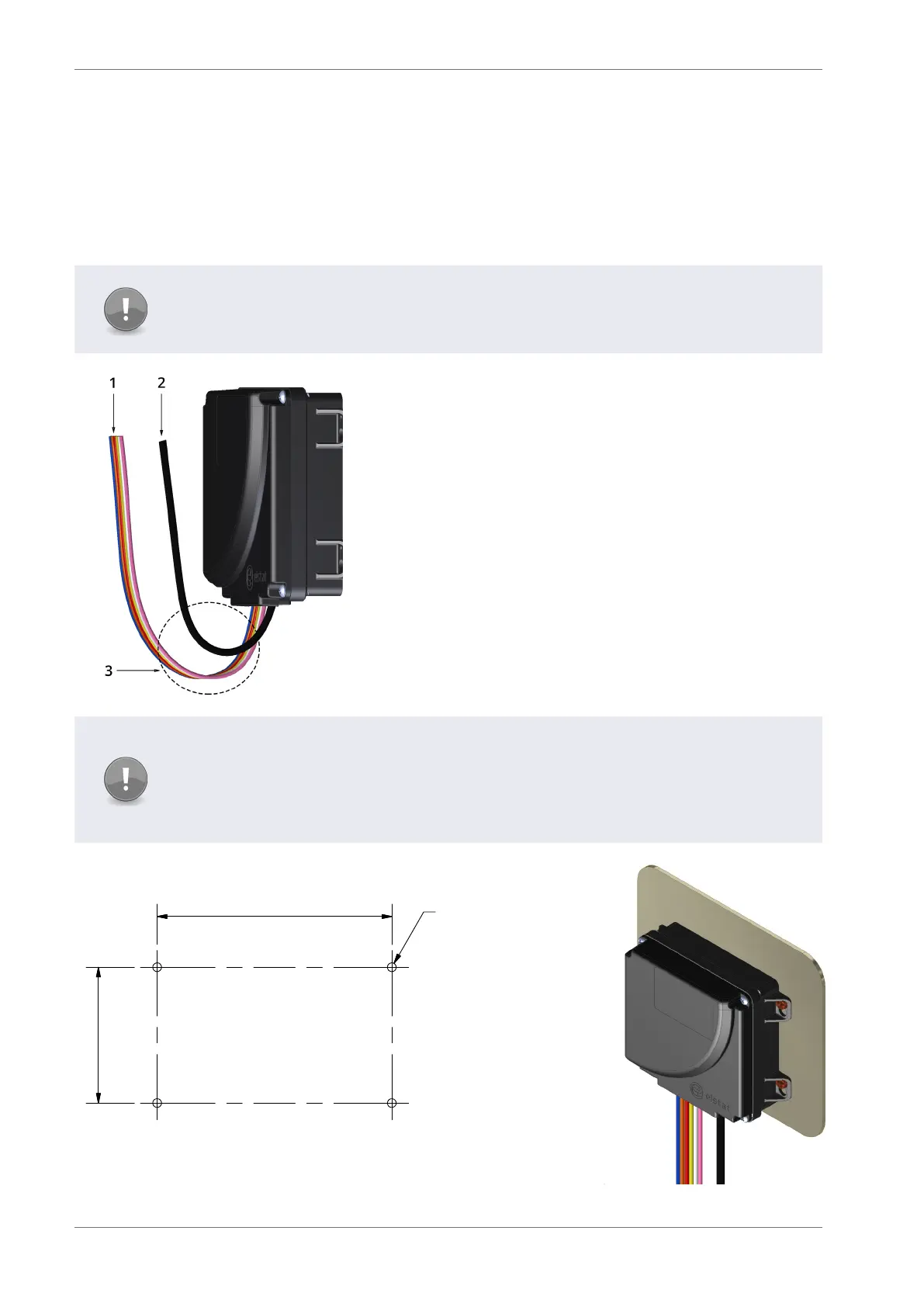
Cable routing to the PSM is critical as water can trace or follow
the cable downwards.
Therefore, immediately prior to the connection to the power
supply module, a drip-loop must be formed in all wiring.
Cable routing looms must not be secured to hot pipes or
vibrating components.
Secure cable routing looms with clips where ever possible.
1 - High voltage connection cable (six way)
2 - Interface cable PSM & CDM
3 - Drip loop
Note
The Water Ingress Protection ratings (IP ratings) are only valid when the product is
mounted in the recommended orientation shown below.
Failure to follow these guidelines will invalidate the designed levels of Ingress Protection
and any subsequent damage incurred will not be covered under the warranty terms.
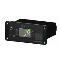
The dimensions of the xing holes for mounting the PSM:
6
4
.
5
m
m
121 mm
4.5 mm4 x
Example of the Power Supply Module mounted.