Communication Connections
5.1.2 Connector J4 (Ethernet RJ45 Connection)
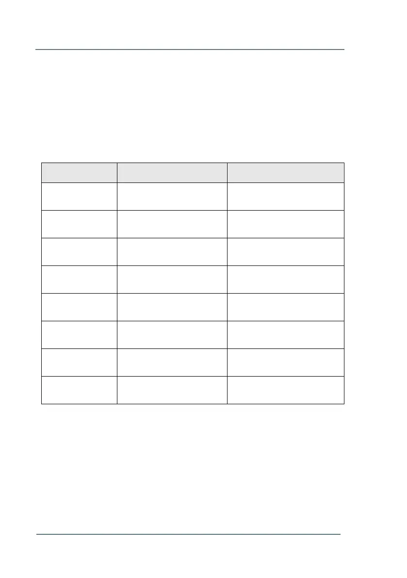
Table 5 shows an overview of the connections on J4.
When connecting the communication through this connector, the TB2
connectors should be left disconnected. See Chapter 5.1.1 - Connector
TB2 (p.15).
RJ45 Power over Ethernet
(Power -) *
RJ45 Power over Ethernet
(Power -) *
Receive - / PoE Receive
-
RJ45 Ethernet receive - **
RJ45 Power over Ethernet
(Power +) *
RJ45 Power over Ethernet
(Power +) *
Receive + / PoE Receive
+
RJ45 Ethernet receive + **
Transmit - / PoE Transmit
-
RJ45 Ethernet transmit - **
Transmit + / PoE
Transmit +
RJ45 Ethernet transmit + **
* Power over Ethernet (POE) complies with IEEE 802.3af. It requires an external
power supply, limited-energy (max. 48 Vdc max. 3 A), reinforced insulation is provided
between input and output by safety transformer and distances on PCB.
** Cable must be UTP, STP or FTP with category 5E or 6. Maximum cable length is
100 meter.
Table 5: Communication Connector, J4
 Loading...