Communication Connections
5.2 Communication Connector TB3
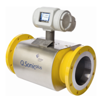
Besides a network connection, the Ultrasonic Flow Meter Series 6 is capable
of communicating through:
Serial communication (either RS232 or RS485), protocol U_DATA
or ModBus
o Cable cross-sectional size area (CSA) min 0.5 mm²
o RS232: 3 x 2 cable max. 15m and 2.5ohm/wire
o RS485: 2 x 2 cable max. 700m
Frequency output
o Externally powered: 24 VDC, 10 kOhm pull-up resistor
(max 30VDC @ 12mA)
o Range programmable up to 5kHz
o Possible outputs can be selected with SonicExplorer
Analogue output
o Internally powered (active): 24VDC, 40 mA maximum
o Possible outputs can be selected with SonicExplorer.
Digital output
o Externally powered: 24 VDC, 10 kOhm pull-up resistor
o Can be set as ‘Low frequency’ or as a status output
(e.g. data valid, flow direction)
o Possible outputs can be selected with SonicExplorer.
All these communication possibilities are located on the TB3 connector.
Maximum cable core is 1.5 mm². Table 6 shows an overview of the
connections.
 Loading...