EasyManuals Logo

Elster 6 Series Wiring Instructions

Elster 6 Series
31 pages
To Next Page IconTo Next Page
To Previous Page IconTo Previous Page
Page #24 background imageLoading...
Page #24 background image
Optional DSL Modem
7
Page 24 of 31
Wiring Instructions
UFM Series 6
7.1.4 DIP Switch 4
This switch is to set the noise reduction level:
ON, 6dB SNR: Standard noise reduction level (6 dB).
OFF, 9dB SNR: Higher noise reduction level (9 dB).
7.2 LED Indication
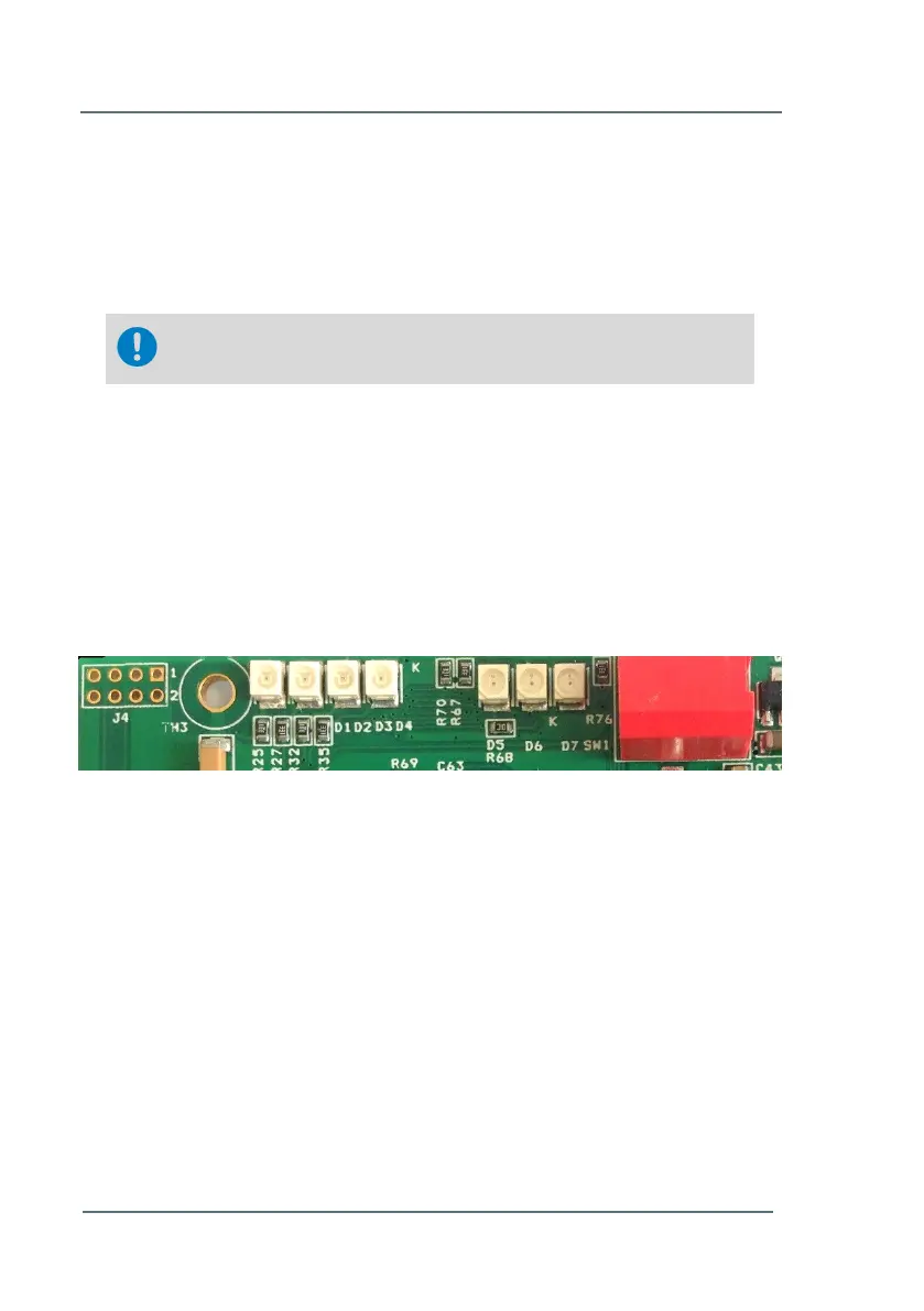
The DSL modem contains LED’s that provide communication status
information. Figure 7-2 shows the position of the LED’s on the modem. The
first 4 LED’s are regarding the VDSL connection. The last 3 LED’s are
regarding the internal LAN connection. Table 8 shows their functionality.
This switch is only relevant if this modem is the master
modem. See Chapter 7.1.1 - DIP Switch 1 (p.23)
Figure 7-2: LED Indication on the DSL Modem
D1 D2 D3 D4 D5 D6 D7
dD3

Other manuals for Elster 6 Series

Questions and Answers:

Question and Answer IconNeed help?

Do you have a question about the Elster 6 Series and is the answer not in the manual?

Elster 6 Series Specifications

General IconGeneral
BrandElster
Model6 Series
CategoryMeasuring Instruments
LanguageEnglish

Related product manuals