if the socket screws are loose enough. When the SPU does not rotate
smoothly please contact Elster or your local representative. After rotating the
SPU, fasten the three socket screws back on.
4 Power Connection (TB1)
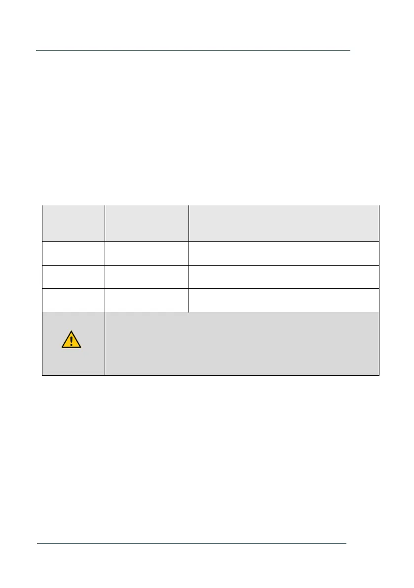
In Table 2 an overview is given of the power connections of the Ultrasonic
Flow Meter Series 6. The position of the power connection is stated in Figure
2-3.
Table 2: Power Connections (TB1)
For choosing the correct cable for wiring the power connection, please refer
to the general instruction in Chapter 3 - Installation Instructions (p.10) and
specific instructions in Table 2.
DC power input 24V nominal
In case the ultrasonic flow meter body is connected to a cathodic
protection system, leave pin number 1 unconnected; as in that case
the ‘earth’ of the external power supply should not be connected.
 Loading...