2 SPU Overview
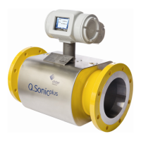
The SPU box contains two separated compartments; a main and a rear
compartment (see Figure 2-1 and Figure 2-2). The main compartment can
be opened from the side of the SPU and contains the most important circuit
boards. All connections herein are factory set and should not be adjusted on
site. It is strongly advised to only open this compartment after consultation
with Elster.
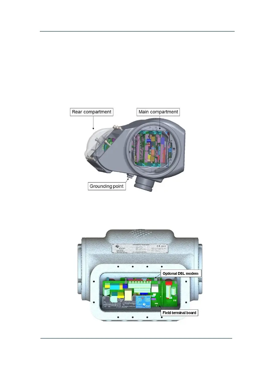
For all external connections to the meter the connection holes in the bottom
of the rear compartment should be used (see Figure 2-2). Five connection
holes are provided; the thread type can be either M20 or ½” NPT. Unused
Figure 2-1: SPU Compartments
Figure 2-2: Rear Compartment
 Loading...