32 A1120/40 - Electronic Polyphase Meter
© Elster Metering Limited - M181 001 2G - 5/2010
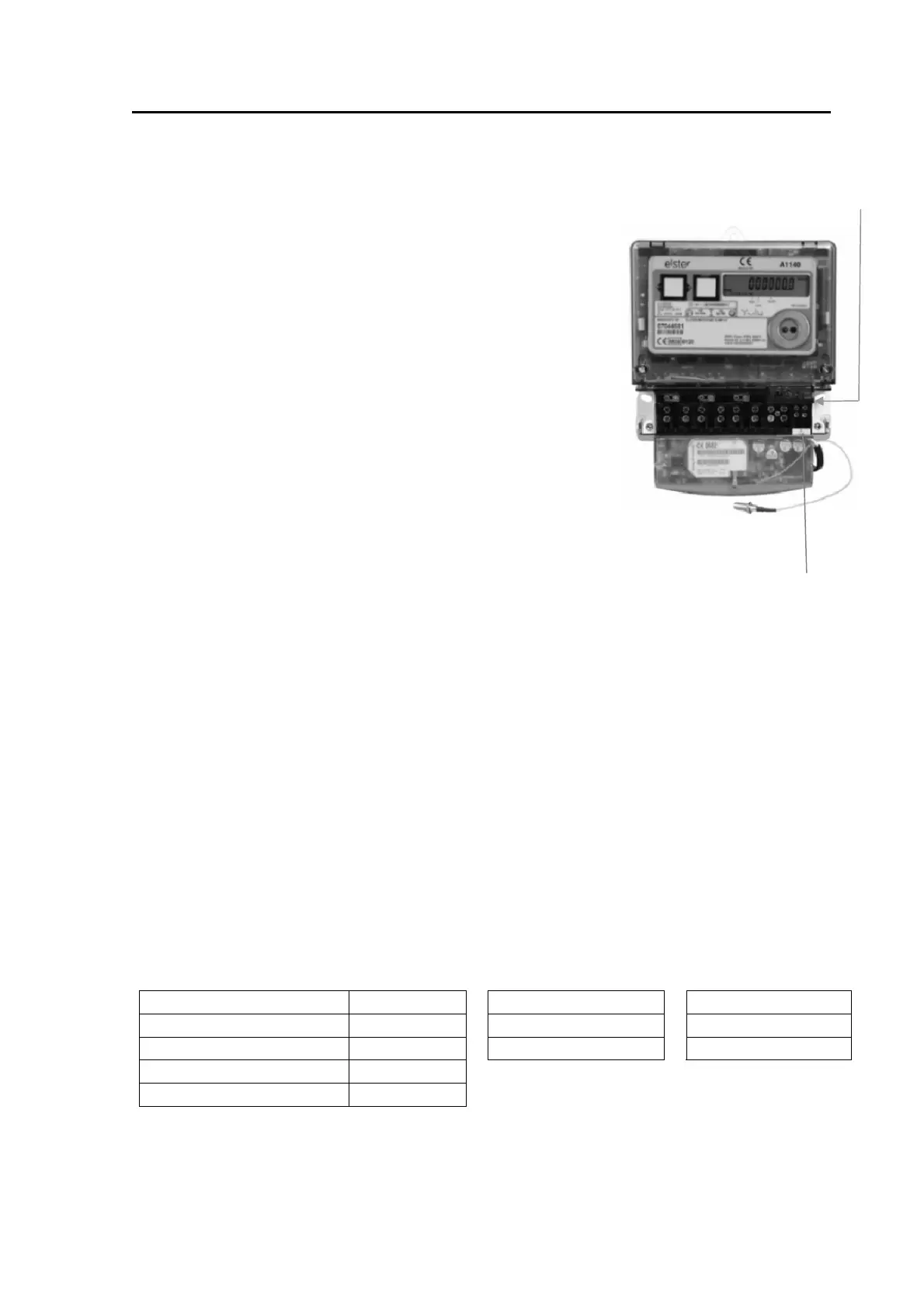
20 MODULE/BATTERY CARRIER
A Special housing can be supplied as an option for a Module or External Battery. Molex Connector
20.1 Communications Module
Simple installation
Snap in position
Sealable (under the terminal cover)
Connects to the meter via a 'RJ11' connector
Refer to Chapter 3 (M181 001 3) Communications Modules
20.2 External Battery Module
Simple installation
Snap in position
Sealable (under the terminal cover)
Connects to the meter via a 'Molex' connector
Refer to Appendix D, External Battery Module
21 OUTPUT
An optional output can be provided. This output can be set at manufacture to one of the following
options:
SO output, floating, customer configurable pulse duration/value
SO output, floating, replicating the kWh LED
SO output, floating, replicating the kvarh LED
100mA relay output, floating, customer configurable pulse duration/value
100mA relay output, floating, replicating the kWh LED
100mA relay output, floating, replicating the kvarh LED
300mA relay output, floating, customer configurable pulse duration/value
The outputs have the following characteristics:
SO Output 100 mA Relay Output 300mA Relay Output
Maximum voltage (Umax) 27V d.c. 230V a.c or d.c 230V a.c
Maximum current in On-state 27 mA 100mA 300mA
Minimum current in On-state 10 mA
Maximum current in Off-state 2 mA
The output is connected using two 3.2mm diameter terminals (See Figure 5).
The pulse output meets the requirements of IEC 62053-31.
RJ11 Connector