Operating & Maintenance Instructions 41
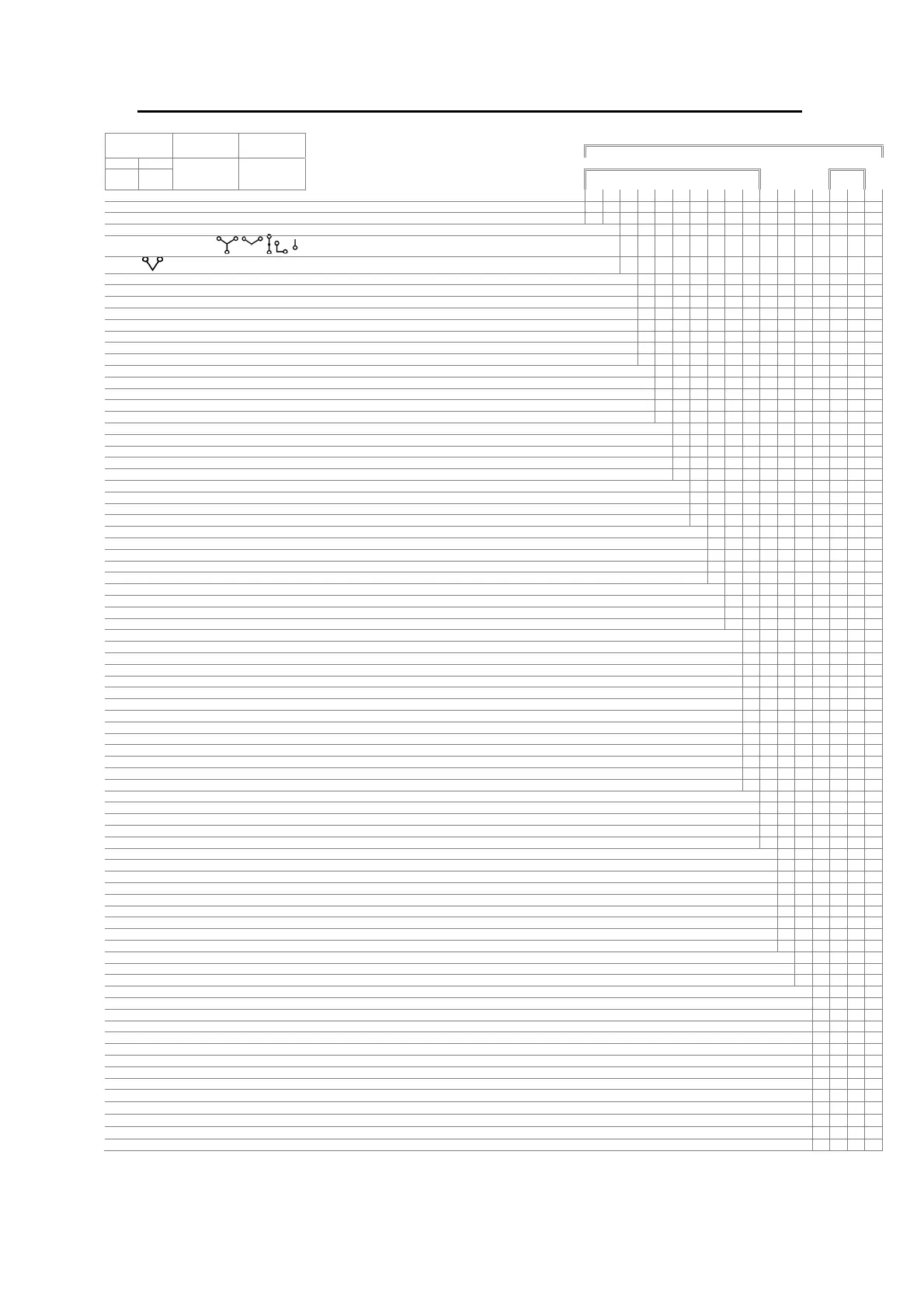
POLYPHASE (A1120/A1140) MODEL CODE
V
ref
I
b
I
max
MODEL
L-L L-N
TYPE (nameplate)
example:
L M 3 A A B N N B B B N N B - A N
PRODUCT/TERMINATION
Polyphase, BS/DIN termination L M
SERVICE TYPE
3Ph 4W for use on:
3
3Ph 3W
2
CURRENT RANGE
Direct Connected 20A – * (* is any multiple of Ib up to 100A maximum) A
Direct Connected 10A – * (* is any multiple of Ib up to 100A maximum) B
Direct Connected 5A – * (* is any multiple of Ib up to 100A maximum) C
CT Operated 1A – 2A L
CT Operated 5A – 10A M
CT Operated 1A – 10A N
Direct Connected (10A - 100A) -40ْ to 70ْ C operation P
VOLTAGE
220 - 240V (L - N) (See note 2 for Ref voltage ranges) A
220 - 240V (L - L) (See note 2 for Ref voltage ranges) (LM2****** variants only) B
105 - 127V (L - N) (See note 2 for Ref voltage ranges) Not OFGEM Approved C
105 - 127V (L - L) (See note 2 for Ref voltage ranges) (LM2****** variants only) Not OFGEM Approved D
ACCURACY CLASS
50 Hz Cl.1 kWh, Cl.2 kvarh (IEC 62053-21, 23 see note 1) B
50 Hz Cl.2 kWh, Cl.3 kvarh (IEC 62053-21, 23 see note 1) C
60 Hz Cl.1 kWh, Cl.2 kvarh (IEC 62053-21, 23 see note 1) Not OFGEM Approved E
60 Hz Cl.2 kWh, Cl.3 kvarh (IEC 62053-21, 23 see note 1) Not OFGEM Approved F
HARDWARE - SWITCHES
No tamper detect switches N
Two tamper detect switches B
Terminal cover tamper detect switch and CT ratio programming protection switch C
HARDWARE - BUTTONS
No buttons
N
Two buttons B
Backlit LCD with no buttons C
Backlit LCD with twom buttons D
HARDWARE - BATTERY
No external battery connection
N
External Battery connection. Note! External battery module cannot be fitted when an RS232 comms module is fitted B
Supercapacitor/External battery/RS485 module connection C
OPERATIONAL MODES
Import kWh only
B
Import kWh, Q1 and Q4 kvarh
C
Import kWh, Q1, Q2, Q3, Q4 kvarh and Imp kVAh
D
Imp/Exp kWh
E
Imp/Exp kWh, Q1, Q2, Q3, and Q4 kvarh
F
Imp/Exp kWh and Imp/Exp kVAh
G
Imp/Exp kWh, Q1, Q2, Q3, Q4 kvarh and Imp/Exp kVAh
H
Import kWh only (Power Flow Insensitive)
J
Import kWh, Q1 and Q4 kvarh (Power Flow Insensitive)
K
Import kWh, Q1, Q2, Q3, Q4 kvarh and Imp kVAh (Power Flow Insensitive)
L
Import kWh only (Theft Resistant Measurement)
R
Import kWh, Q1 and Q4 kvarh (Theft Resistant Measurement)
S
Import kWh, Q1, Q2, Q3, Q4 kvarh and Imp kVAh (Theft Resistant Measurement)
T
TARIFFS
A1120 Multi Rate
B
A1140 Multi Rate (with load profile)
C
A1120 Multi Rate with password protected register zeroing and zero level time shift
D
A1140 (with load profile) Multi Rate with password protected register zeroing and zero level time shift
E
AUXILIARY OUTPUT
No Output
N
SO output, floating, 2 aux terminals. 12 kV isolation (Configurable pulse duration/value) 27V DA only
P
SO output, floating, 2 aux terminals. 12 kV isolation, replicating centre LED (kWh) 27V DA only
A
SO output, floating, 2 aux terminals. 12 kV isolation, replicating left hand LED (kvarh) 27V DA only
R
Relay output, floating, 2 aux terminals. 12 kV isolation (Configurable pulse duration/value) 230V AC, DC
S
Relay output, floating, 2 aux terminals. 12 kV isolation, replicating centre LED (kWh) 230V AC, DC
D
Relay output, floating, 2 aux terminals. 12 kV isolation, replicating left hand LED (kvarh) 230V AC, DC
U
300mA Relay output, floating, 2 aux terminals, 12kV isolation, indicating tariff/MD state, 230V a.c only
T
COMMUNICATIONS
No Serial Comms N
RS232 serial Comms Note! RS232 Comms module cannot be fitted when an external battery module is fitted R
OTHER OPTIONS
Standard (Extended) Terminal cover B
Standard (Extended) Terminal cover with cut-out C
Standard (Extended) Terminal plus 9.0mm main terminal bores D
Short Terminal Cover E
Standard (Extended) Terminal cover with additional voltage terminals F
Standard (Extended) Terminal cover with cut-out and additional voltage terminals G
Standard (Extended) Terminal cover plus 9.0 mm mail terminal bores and additional voltage terminals H
Standard (Extended) Terminal cover plus 9.5 mm main terminal bores J
Standard (Extended) Terminal cover and main cover with voltage disconnect protection
K
Standard (Extended) Terminal cover with slotted head screws
L
Standard (Extended) Terminal cover with cut-out and slotted head screws
M
Short terminal cover with slotted head screws
P
Figure 1 - Model Code