Operating & Maintenance Instructions 33
WARNING
See Warning in Section 26.6 regarding additional protection for circuits connected to the
auxiliary terminals.
21.1 Customer Configurable Auxiliary Output (SO and Relay)
Retransmit
The customer configurable auxiliary output can be sourced (using the Power Master Unit) to
transmit pulses from one of the following registers:
• Cumulative registers (Import or export Wh - Q1, Q2, Q3 or Q4 - VAh 1 or VAh 2)
• Customer defined registers (Register 1 or Register 2)
The pulse value and width can be configured as follows:
Pulse value 1, 2, 4, 5, 10, 20, 40, 50, 100, 200, 250
Pulse width (ms) 10, 20, 30, 40, 50, 60, 80, 100, 120, 160, 200, 250
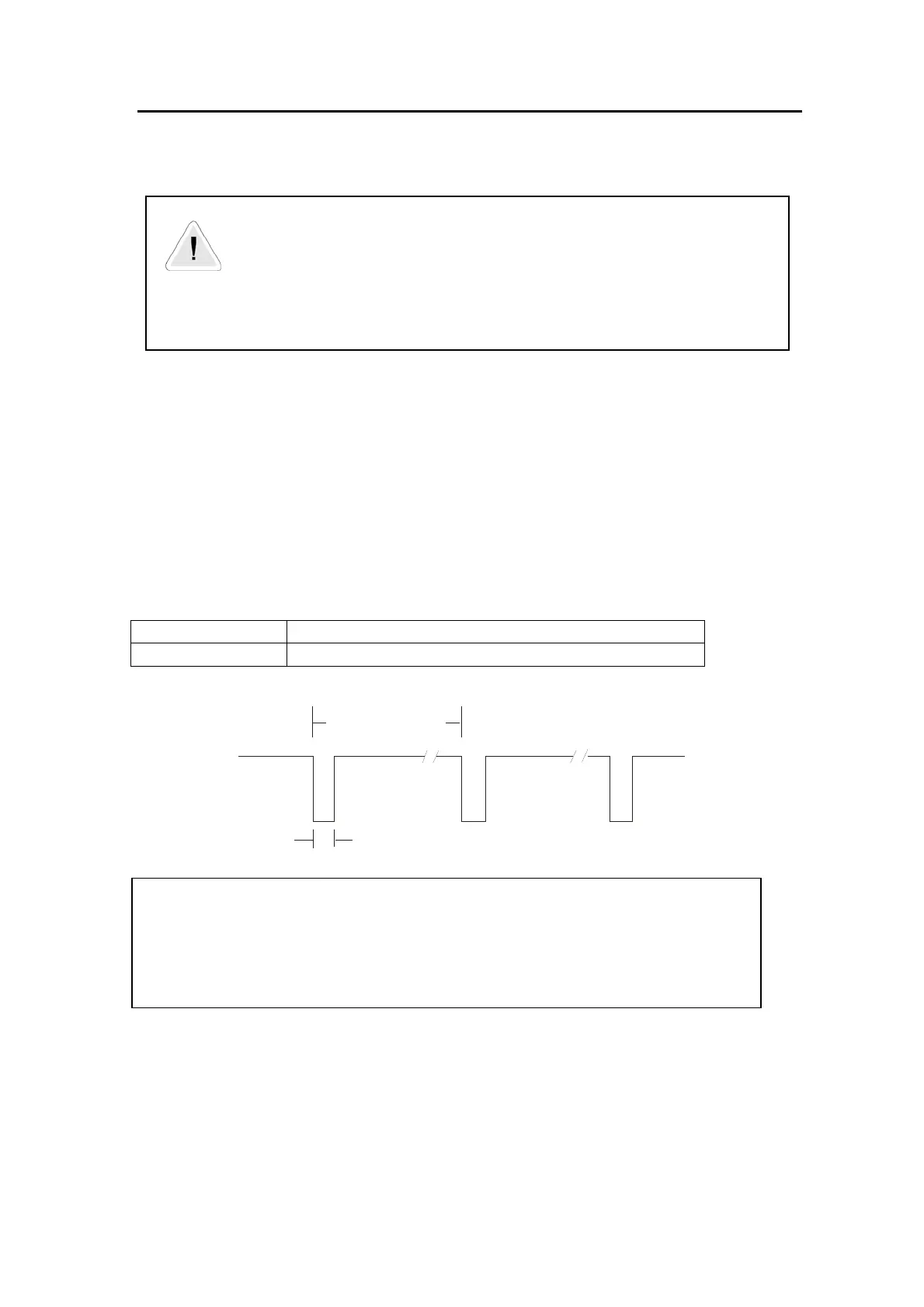
High Impedance
Low Impedance
Energy = Puls e
consum ed ) value
Pulse width
Caution
Care should be taken in selecting the combination of pulse width and pulses/unit.
Avoid combinations that may give insufficient spacing between pulses at maximum load.
To ensure correct operation a maximum of 10 pulses/sec should not be exceeded.
When the meter is in anti-creep mode the output does not pulse.
Rate Indication
The output can be sourced (using the Power Master Unit) to provide indication of an active rate.
The output becomes low impedance if any one of a selected combination of TOU or MD TOU tariffs
is activate.