Operating & Maintenance Instructions 47
TO LOAD
A
B
N
C
+
-
20
21
A
B
C
JL 3013 312B
LM3 ***
Rx
Tx
0V
+V
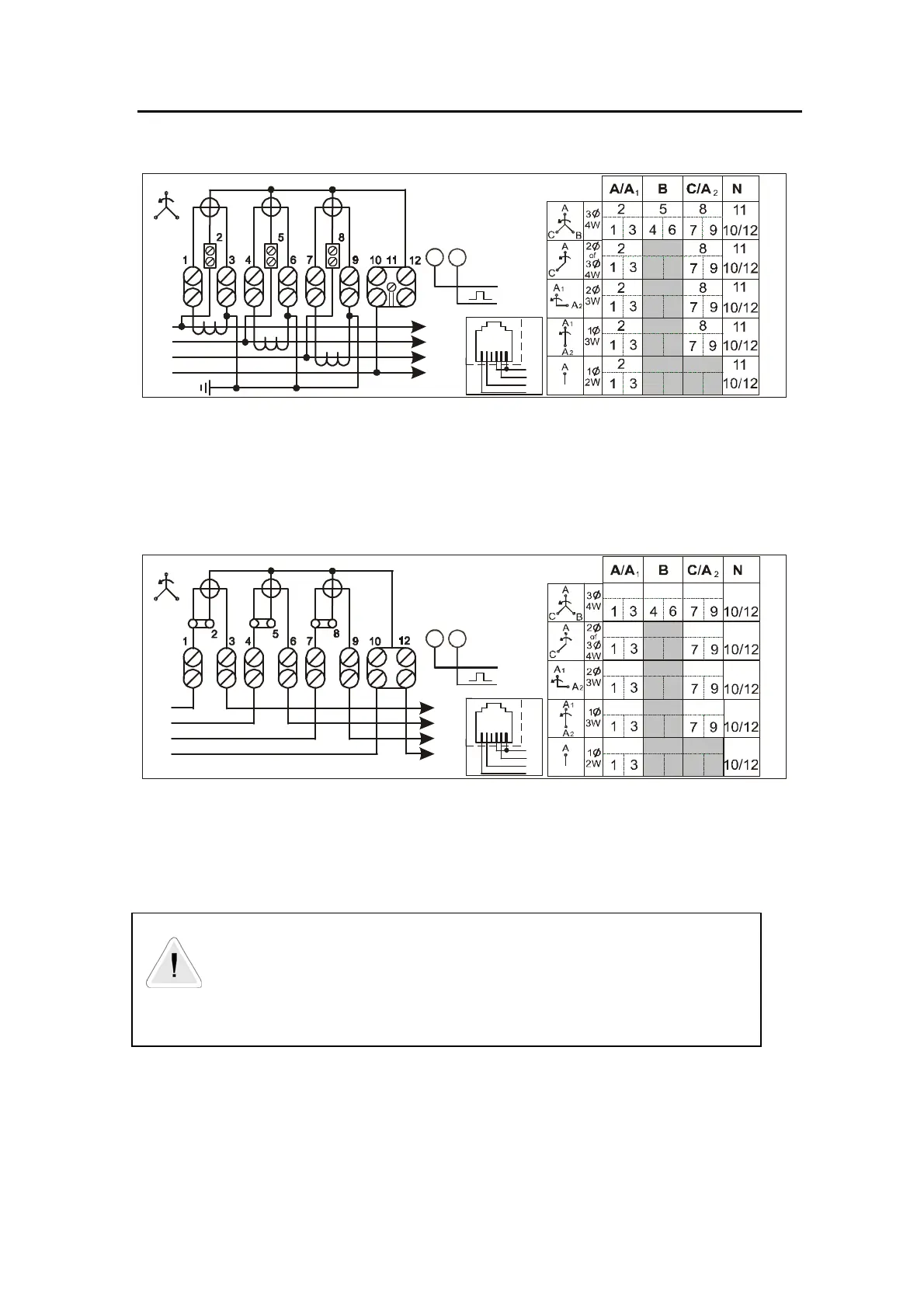
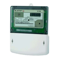
3 phase 4 wire, CT operated
TO LOAD
A
B
N
C
+
-
20
21
A
B
C
JL 3013 311B
LM3 ***
Rx
Tx
0V
+V
3 phase 4 wire, Direct connected
Note: These diagrams are examples only.
WARNING
Meters must be connected according to the diagram fitted under the meter terminal cover.
Figure 5A – Terminal Configurations


 To Next Page