Copyright 2005 by ELTRA GmbH Germany – January 2005 – Operation Manual ON-900
1.4 Data interfaces
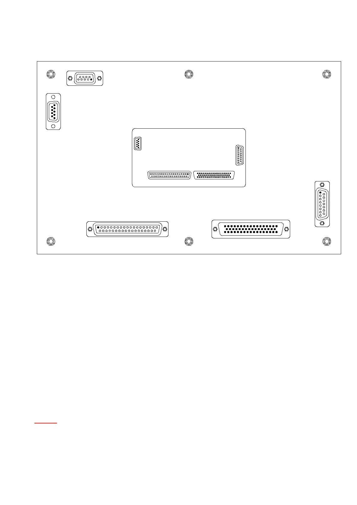
Rear side of UNI 1.3 board:
1 Pear serial interface
2 PC connection
3 Analog input/output signals
4 Digital input/output signals
5 Autoloader connection
When all the units are connected to the mains power, then data connections can be made.
The plugs are all different from each other, so that they cannot be interchanged. The required
data cables are included if the additional units are supplied. These are adapted to the
interfaces when the analysers are put into operation in our company.
As the balance transfers the weight to the PC, its serial interface must be programmed.
The computer is already provided with an operating system and software for controlling the
analyser.
UNOTE:U For all instructions on operating the PC software refer to the Help-function of
the software.
2
3
4
5
1
2-3-1
Analog I/O
Digital I/O
Loader
Microcontroller
board UNI 1.4
Part No.18467
PC
 Loading...