Copyright 2005 by ELTRA GmbH Germany – January 2005 – Operation Manual ON-900
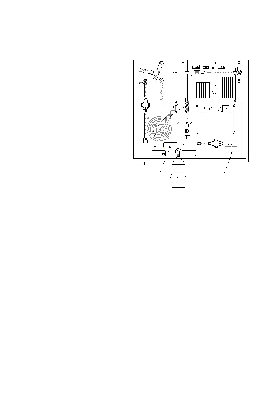
1.5 Gas connections
1 Cooling water outlet
2 Cooling water inlet
3 Outlet water to tank
4 Secondary cycle outlet
5 Water tap inlet
6 Compressed air 4-6 bar
7 Gas outlet
8 Carrier gas inlet 2-4 bar
Two gas connections are necessary for the operation of the analyser. The required tubes are
included in delivery. See above drawing
Tube (8) is for the carrier gas supply, it is soft and transparent.
Tube (6) for the compressed air is harder and opaque.
These are delivered, provided with screw fittings for pressure regulators.
An R¼" inner thread as well as the corresponding copper seals are also provided.
Tube fitting (8) connects the analyser with a helium carrier gas bottle
These connections must be very secure, since the operating pressure in the tube is 2-4 bar
(30 to 60 psi). Gas connection (6) is for the compressed air supply to the pneumatic furnace
lock.
Gas connection (7) is for drawing off outlet gas. It is generally not in use, however, since only
low quantities of CO2 and even lower quantities of N result from the sample combustion.
When the analyser's mains switch is set to position 2 a valve opens, and the carrier gas
flows through the gas tubes. The flow rate is stabilised after several seconds to 15 l/h and
can be read from the lower flow indicator. At the same time the cooling water pump starts.
5
2-4-1
6
1
3
4
2
7
8
23 0V AC 1~ N 50 /60 H z
ma x. 75 0 0 Wa tt s
40 0V AC 3~ N 50 /60 H z
(30-60psi)
p u re
F us e
slow blow
4A
Gasoutlet
Com pre ssed A ir
4-6 bar (60- 90psi)
Com pre ssed A ir
4-6 bar (60- 90psi)
 Loading...