EM Test esd NX30
Instruction Manual V 1.00.7 13 / 33
4.2.5 Interlock (esd NX30 only)
The esd NX30 has an integrated interlock system in accordance with standard practice for high voltage test equipment.
This system has the following functions:
Inputs
1. Input for external monitoring purposes of, for example, special coupling networks and access control.
2. Internal emergency off button opens the interlock.
Outputs
1. Operating mode: the esd NX30 can generate no high voltage as long as the interlock is not closed. High voltage genera-
tion is prevented if the interlock is opened during a test procedure.
2. Interlock output for other system devices.
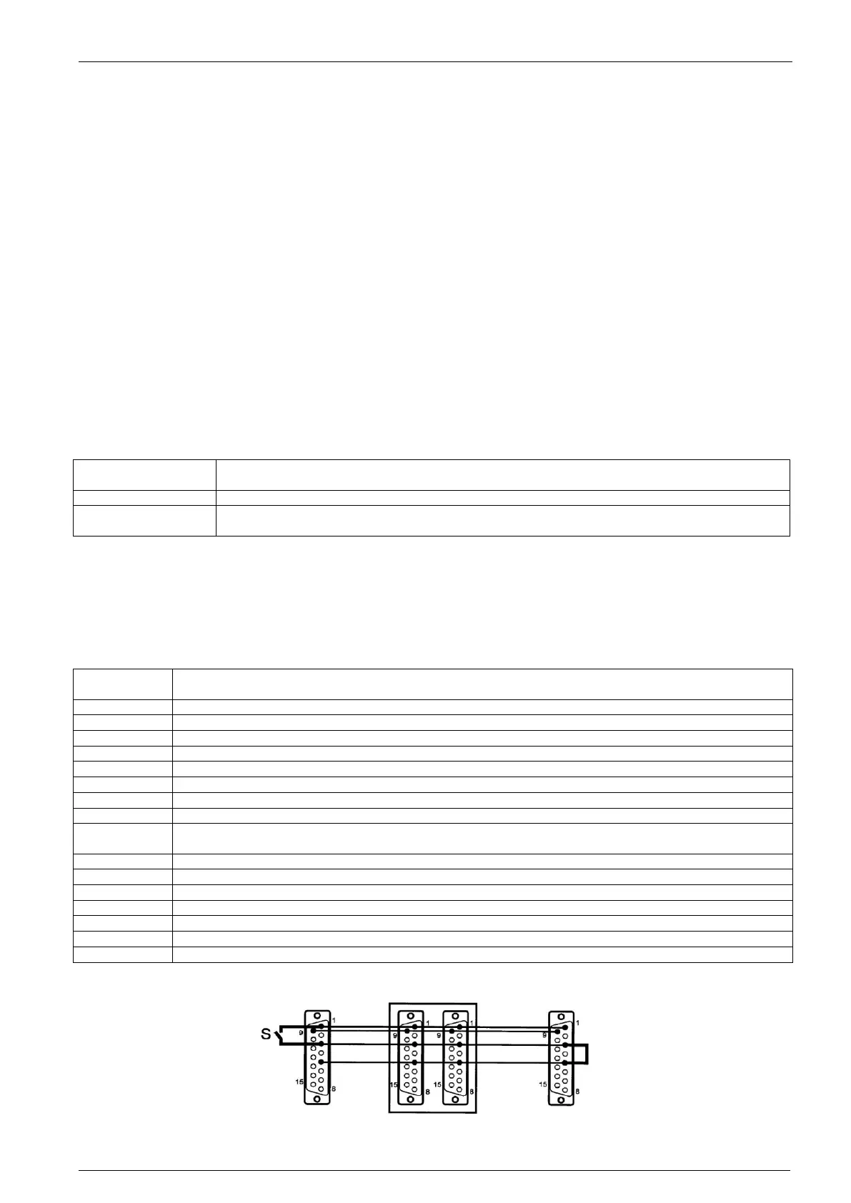
The instrument is equipped with two 15-way connectors for interlock input and output. The interlock loop must always be
correctly terminated at both ends. In achieving this, the interlock wiring must connect all the safety contacts together.
An arbitrary number of instruments or accessories can be incorporated in this safety concept.
The high voltage supply can only be activated if the safety requirements in all the associated devices are fulfilled (emergen-
cy off buttons released, safety contacts closed).
The control of the warning lamps must make use of the interlock feature. The instruments can be switched on and the red
lamp lights up as soon as the interlock circuit is closed.
The pair of terminating connectors supplied must be utilized in the case of not making use of external interlock contacts.
Voltage 48VDC max.
Current 20mA min., 1A max
Max. permissible
cable length:
Correct operation guaranteed up to 10m (screened cable)
Operation should be insured via potential-free switch contacts.
All signals are active low, i.e. switched to GND.
The pin-out of the interlock input and output connector is identical. All the pins are connected together. The connection to pin
3 is made internally through the emergency off button. This link is broken when the internal interlock is activated.
NC, linked through the other connector socket
Interlock input / output (connected inside the instrument)
NC, linked through the other connector socket
Interlock status (triggers the interlock function in the instrument by relay from +12 to +48 V)
NC, linked through the other connector socket
NC, linked through the other connector socket
NC, linked through the other connector socket
Switches warning lamps and peripherals on (active, provided that esd NX30 is switched from standby to
on).
NC, linked through the other connector socket
NC, linked through the other connector socket
NC, linked through the other connector socket
NC, linked through the other connector socket
NC, linked through the other connector socket
NC, linked through the other connector socket
Wiring diagram for the interlock system: