iMX RT1062 OEM Developer’s Kit - User’s Guide
Copyright 2019 © Embedded Artists AB
4.2 SP2a: Power Supplies
The power supply structure on the iMX OEM Carrier board is straight forward. There are two powering
sources, selected via J29:
1. +5V DC via power jack (J1). 2.1mm inner diameter, 5.5mm outer diameter, center pin
positive. This input has reverse polarity and over-voltage protection.
o This powering source is always needed in stand-alone situations or when running
USB Host application that require powering external USB devices. If USB Host is not
used (or used with very low external current consumption), a 5V DC/1 Amp power
supply (5W) is all what is needed. If USB Host is used with high external current
consumption a 5V DC/2-2.5 Amp power supply (10-12.5W) is needed.
2. USB powering via the UART-to-USB Bridge connector (J22).
o The board is normally powered from a PC/laptop via the included USB cable (micro-
B to A cable) when connected to J22 (position 1) in Figure 1). This setup will work in
most cases. However note that not all PC/laptops can provide the needed current. A
powered USB hub or an external power supply can be used in this case.
It is possible to have both the USB cable and external powering connected to the board at the same
time but only one of them will be used at any time. Powering selector, J29, selects either of the two
powering sources. See Figure 12 below where to locate J29.
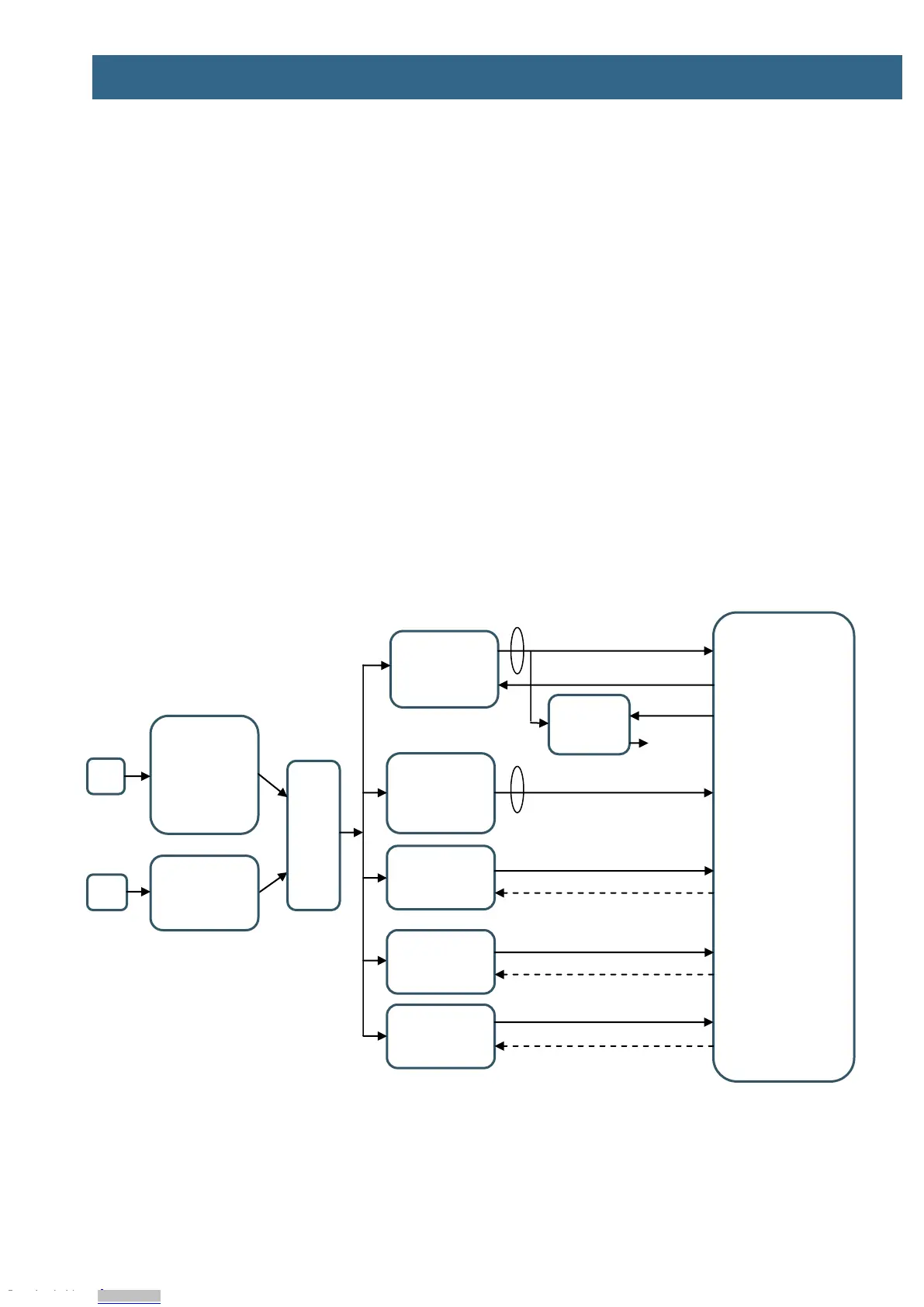
The picture below is principal schematic of the powering structure of the iMX OEM Carrier board.
Figure 11 – Principal Powering Schematic
+5V DC input
Reverse
polarity and
over-voltage
protection
UART-to-USB
bridge
interface
3.3V/25mA
LDO
"Always on"
PERI_3V3
on Carrier
board
3.3V/1.8V SD
card I/O volt.
Downloaded from Arrow.com.Downloaded from Arrow.com.Downloaded from Arrow.com.Downloaded from Arrow.com.Downloaded from Arrow.com.Downloaded from Arrow.com.Downloaded from Arrow.com.Downloaded from Arrow.com.Downloaded from Arrow.com.Downloaded from Arrow.com.Downloaded from Arrow.com.Downloaded from Arrow.com.Downloaded from Arrow.com.Downloaded from Arrow.com.Downloaded from Arrow.com.Downloaded from Arrow.com.