iMX RT1062 OEM Developer’s Kit - User’s Guide
Copyright 2019 © Embedded Artists AB
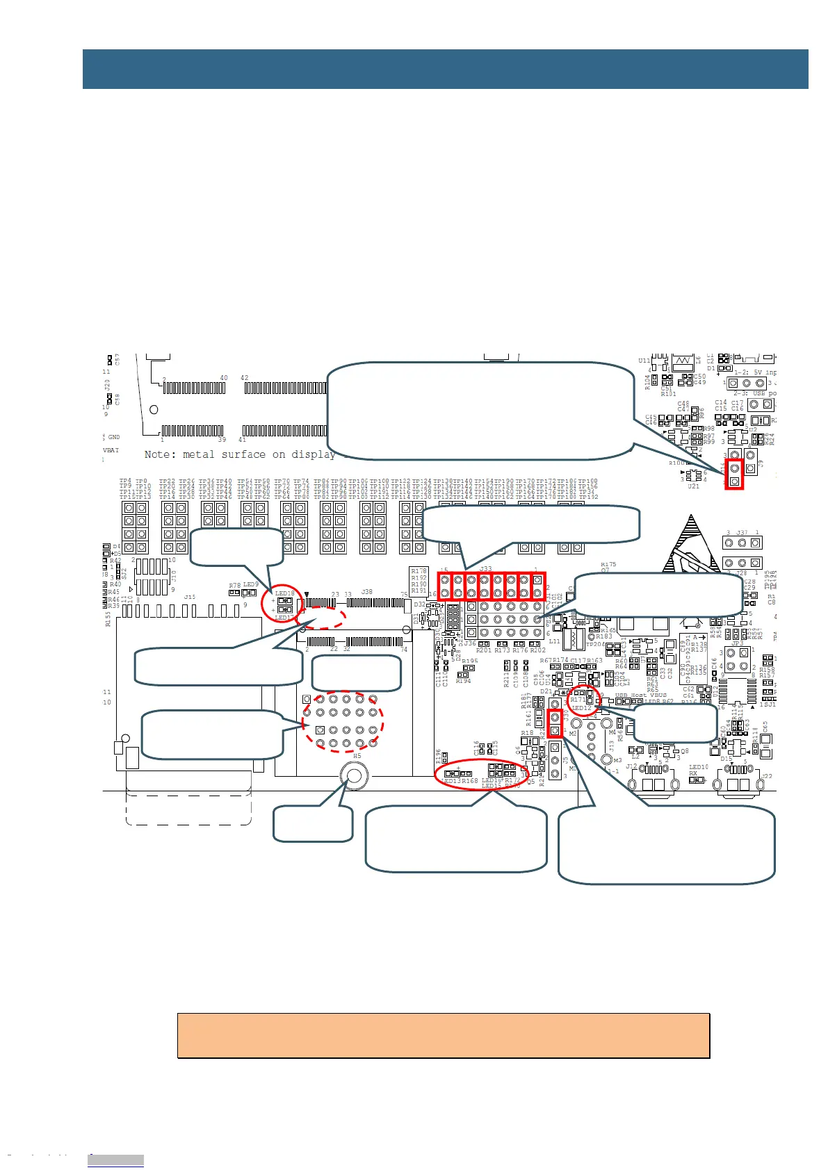
4.15 SP14-SP17: M.2 Power Supply and Control
The M.2 interface is implemented over several schematic pages. The picture below illustrates the main
components, connectors and jumper settings for the interface.
There are several different M.2 standards defined and this design implements the "Key E" version,
which have SDIO, UART and audio (PCM) interfaces along with some control signals. This version of
the M.2 standard is typically used for WiFi/Bluetooth modules.
The M.2 defined signals will not be explained in detail. Consult for M.2 specification for additional
information. The control signal connections used in this M.2 interface has been defined together with
Murata and Cypress.
Figure 26 – M.2 Interface
According to the M.2 specification, the SDIO bus interface I/O voltage shall be 1.8V. Jumper J16 shall
be in 1-2 position. In this position, the SDIO voltage is forced to 1.8V whenever an M.2 module is
inserted in the M.2 connector (J38). A ground pin is used to detect this.
Note that the SD memory card connector, J15, and the M.2 connector; J38, both are
connected to the SDIO bus. Only one interface at a time can be used.
SD_VSEL Ctrl
J16
1-2 (lower pos): Controlled by GPIO_B1_14 but forced to
1.8V VDDIO for SDIO when M.2 module inserted (default)
2-3 (upper pos): Forced 1.8V VDDIO for SDIO
Open: Forced 3.3V VDDIO for SDIO
SDIO Bus Isolation Resistors
R86-R91 on bottom side
VBAT Current Measurement
J30
Lower 1-2 pos: No series resistor (default)
Upper 2-3 pos: 100milliohm series resistor
added
Control signal LEDs
LED13 (VBAT_SEL)
LED16 (AUDIO_CODEC_MUX_CTRL1)
LED15 (AUDIO_CODEC_MUX_CTRL2)
Debug Interfaces
From up to down: J31, J27, J36
Control and UART Isolation Jumpers
J33
Debug interfaces
J34 and J35
Access from bottom side
Downloaded from Arrow.com.Downloaded from Arrow.com.Downloaded from Arrow.com.Downloaded from Arrow.com.Downloaded from Arrow.com.Downloaded from Arrow.com.Downloaded from Arrow.com.Downloaded from Arrow.com.Downloaded from Arrow.com.Downloaded from Arrow.com.Downloaded from Arrow.com.Downloaded from Arrow.com.Downloaded from Arrow.com.Downloaded from Arrow.com.Downloaded from Arrow.com.Downloaded from Arrow.com.Downloaded from Arrow.com.Downloaded from Arrow.com.Downloaded from Arrow.com.Downloaded from Arrow.com.Downloaded from Arrow.com.Downloaded from Arrow.com.Downloaded from Arrow.com.Downloaded from Arrow.com.Downloaded from Arrow.com.Downloaded from Arrow.com.Downloaded from Arrow.com.Downloaded from Arrow.com.Downloaded from Arrow.com.Downloaded from Arrow.com.Downloaded from Arrow.com.