iMX RT1062 OEM Developer’s Kit - User’s Guide
Copyright 2019 © Embedded Artists AB
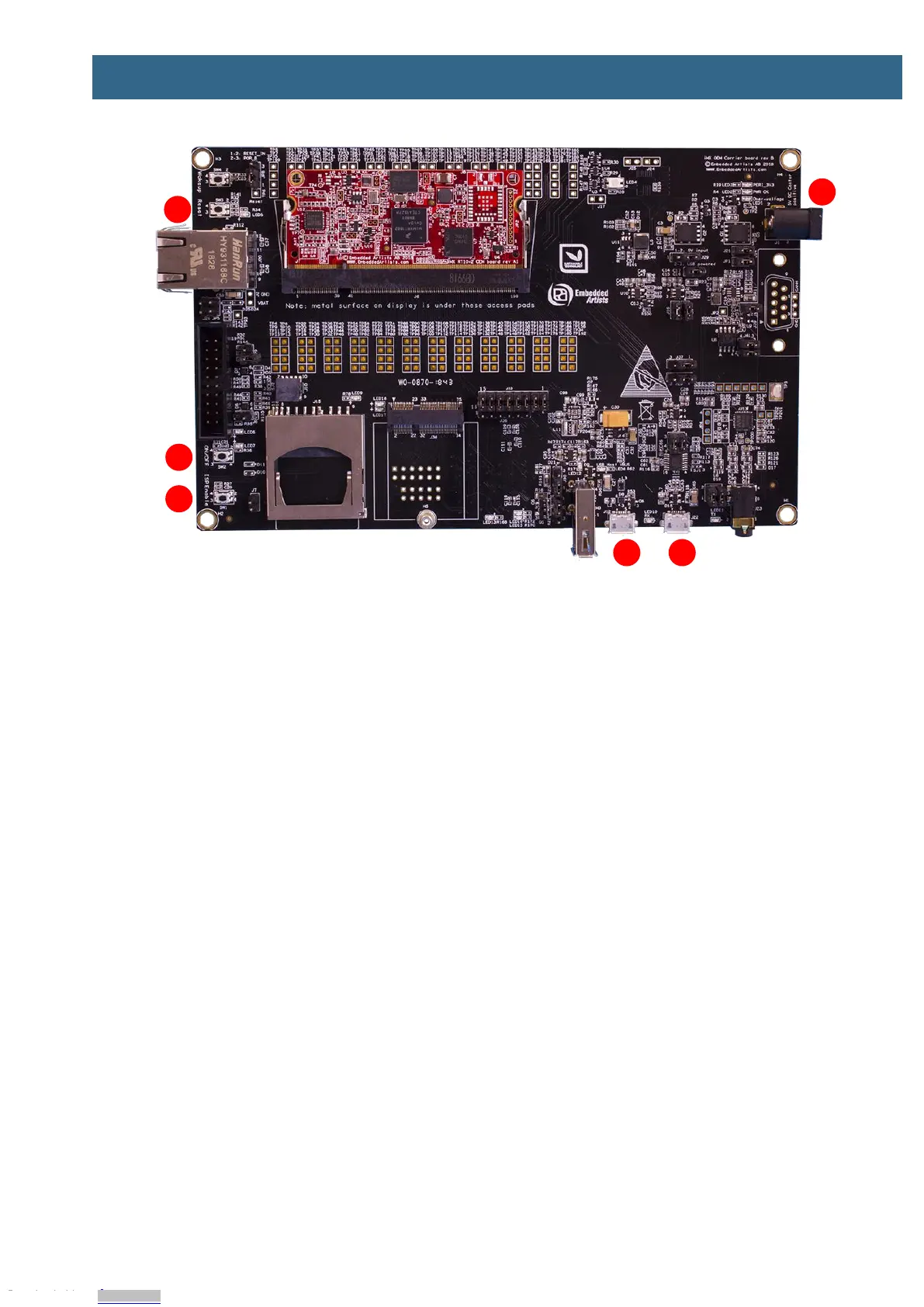
Figure 1 – iMX RT1062 Developer's Kit Top View
1. UART-to-USB bridge - this gives access to the console UART of the i.MX RT1062 MCU. The
USB interface can also power the board.
2. USB OTG connector - this USB interface can, together with a PC application, be used to
program the flash memory of the iMX RT1062 OEM board.
3. Reset push-button - a press will generate a power cycle (in default behavior).
4. ON/OFF push-button - a 5 second press will shut down the main 3.3V supply.
5. ISP Enable push-button - pressing this button while the board power up will place the i.MX
RT1062 is ISP mode (typically used for programming the iMX RT1062 OEM board flash
memory).
6. Alternative power supply input - this is an alternative power supply input, 5V/1A DC, via a
2.1mm power jack. The center position is the positive terminal.
Figure 10 in chapter 4 gives a slightly more detailed presentation of all interfaces and connectors on
the board.
Figure 2 below illustrates the bottom side of the iMX OEM Carrier board. A 4.3 inch LCD with
capacitive touch panel is mounted there. When developing graphical applications, this side is typically
turned up.
Downloaded from Arrow.com.Downloaded from Arrow.com.Downloaded from Arrow.com.Downloaded from Arrow.com.Downloaded from Arrow.com.Downloaded from Arrow.com.Downloaded from Arrow.com.