Introduction
SD32+
System
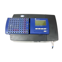
Amplifier Connection Port – This port allows the Headbox to be physically connected to the
amplifier (this process is referred to as “docking” the Headbox). See Figure 2. the headbox amplifier
connection port for an illustration of this port.
Figure 2. the headbox amplifier connection port
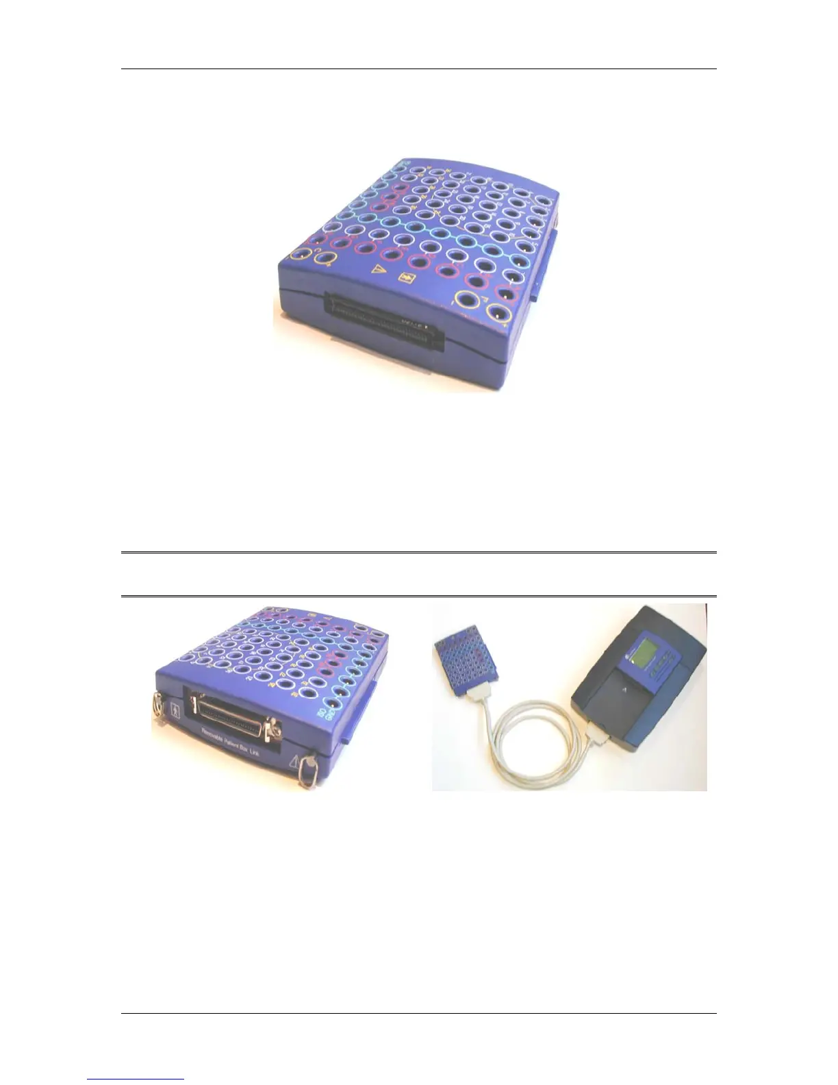
Removable Patient Box (Headbox) Link Port – This port connects the Headbox to the amplifier
using the six-foot Headbox to Amplifier Cable. The cable allows users to place the Headbox near
the patient and allows the patient to be easily disconnected from the amplifier without having to
remove electrodes from the patient. The cable should be kept clear of other devices or cables in
order to achieve the best signal performance. See Figure 3. removable patient box (headbox) link for
an illustration of this port. See Figure 4. headbox to amplifier cable for an illustration of this cable.
Note: When the Headbox’s Removable Patient Box Link port is not in use replace the plastic
cover provided with the SD32+ amplifier to prevent dust build-up on this connector.
Figure 3. removable patient box (headbox) link
port
Figure 4. headbox to amplifier cable
electrode sockets
The Headbox has six types of electrode sockets: Monopolar, Bipolar, Neutral (NE), Isolated
Ground (ISO GND), Temperature, and Calibration. Figure 5. headbox electrode sockets displays the
Headbox’s general appearance and the layout of the electrode sockets.
12