SD32+
System Introduction
3.6.
Sandman elink™
adapter
The Sandman elink adapter serves as a bridge to “link” the SD32+ amplifier to the computer. This
enables the computer to send programming commands to, and receive sleep study data from, the
SD32+ amplifier.
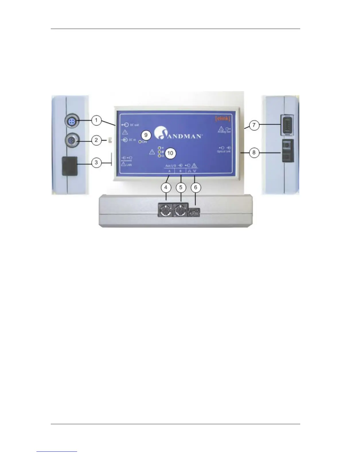
The following figures show the Sandman elink adapter:
Figure 8. Sandman elink adapter
1. DC OUT - (Circular, 4 contact, Female, Triad connector). Supplies the SD32+ amplifier
with DC voltage.
2. DC IN - (Circular, 4 contact, Male, Triad connector). Isolated DC input Connector; accepts
the DC voltage output from the External Medical Grade AC/DC Adapter.
3. LAN - (RJ45 connector) Local Area Network, 10/100 Mbps Ethernet interface.
4. Serial AUX I/O - (A) - (Circular, 8 contact, Female, HiRose connector). Connects to
peripheral devices using the RS232 communications protocol. Only use devices approved
by Embla Systems for use with the Sandman elink adapter.
5. Serial AUX I/O (B) - Same as “Serial AUX I/O – (A)” above.
6. Trigger I/O - Reserved for future use.
7. Analog out Link - Reserved for future use.
8. OPTICAL LINK – (Dual-strand fiber optic connector) Used to communicate with the
SD32+ amplifier.
9. Power on LED - Power status indicator.
10. LAN activity LEDs - Indicate various LAN states.
19