Introduction
SD32+
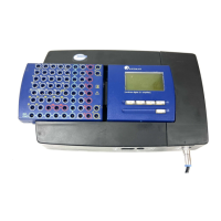
System
14
The following table summarizes the Headbox electrode sockets and their characteristics:
input socket
label
socket type current
type
function Gain setting +
resolution
Max. input
A - H Bi-polar AC Accepts channel signal
input and reference
‘High’
1 µV/8 bits
8mV
p-p
‘Low’
2 µV/bit
128mV
p-p
1 - 24 Mono-polar AC Accepts channel signal
input
‘High’
1 µV/8 bits
8mV
p-p
‘Low’
2 µV/bit
128mV
p-p
25 - 32 Mono-polar AC/DC Accepts channel signal
input
‘High’
1 µV/8 bits
8mV
p-p
‘Low’
2 µV/bit
128mV
p-p
1
‘DC1’
10 µV/bit
640mV
p-p
2
‘DC2’
20 µV/bit
1.28 V
p-p
3
‘DC23’
100 µV/bit
6.4 V
p-p
4
Neutral (NE) N/A N/A References mono-
polar channel inputs
Isolated Ground
(ISO GND)
N/A N/A Connects patient
ground
T
o
(Temperature)
Bi-polar DC Accepts a temperature
probe input when the
Headbox is docked
C (Calibration) Bi-polar AC Generates calibration
pulse output when the
Headbox is docked
Table 4. SD32+ amplifier headbox sockets
1
Includes 28 mV
p-p
offset
2
Includes 140 mV
p-p
offset
3
Includes 280 mV
p-p
offset
4
Includes 1.4 V
p-p
offset