Menu 11 Introduction
Parameter
x.00
Parameter
description format
Keypad and
display
Serial
communications
CT Modbus
RTU
PLC Ladder
programming
CTSoft Menu 0
Advanced parameter
descriptions
146 Commander SK Advanced User Guide
www.controltechniques.com Issue Number: 9
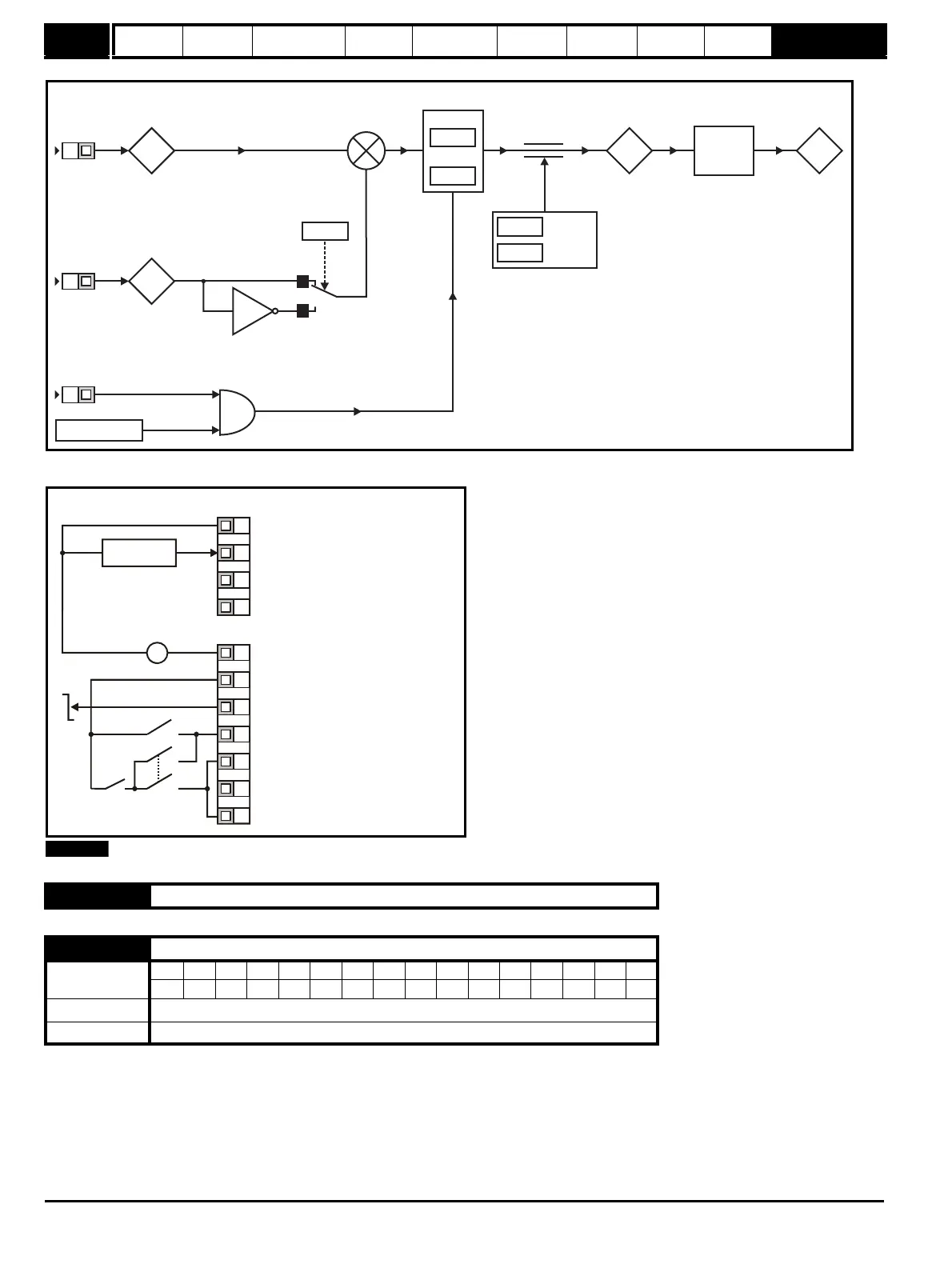
Figure 10-34 PID logic diagram
Figure 10-35 Pr 11.27 = HVAC
Only with V01.04.00 onwards.
The drive software version consists of three numbers xx.yy.zz. xx.yy is displayed in this parameter and zz is displayed in Pr 11.34. Where xx specifies
a change that affects hardware compatibility, yy specifies a change that affects product documentation, and zz specifies a change that does not affect
the product documentation.
11.28 Unused parameter
11.29 Software version {45}
Coding
Bit SP FI DE Txt VM DP ND RA NC NV PT US RW BU PS
21 1 1 1
Range 0.00 to 99.99
Update rate N/A
7.02
7.01
%
T4
T2
x(-1)
0
1
14.06
Invert
14.10
P Gain
14.11
I Gain
PID reference
input
%
PID feedback
input
B7
PID enable
&
Drive healthy
14.13
PID high
limit
14.14
PID low
limit
14.01
%
1.01
Drive
reference
Hz
%to
frequency
conversion
+
_
H: Contacts made
in 'hand' position -
Keypad control
A: Contacts made
in 'auto' position -
Remote current
speed reference
input.
0V
Remote current speed
reference input (A1)
+10V reference output
Not used
+24V output
Drive enable / reset
Run reverse
Remote speed
reference input
V
_
+
Eur & USA
Analog output
(motor speed)
Digital output
(zero speed)
T1
T2
T3
T4
B1
B2
B3
B4
B5
B6
B7
+24V
0V
Auto
run
Hand/Off/Auto
switch
H
A
A
Run forward
Reference
select