Menu 1 Introduction
Parameter
x.00
Parameter
description format
Keypad and
display
Serial
communications
CT Modbus
RTU
PLC Ladder
programming
CTSoft Menu 0
Advanced parameter
descriptions
40 Commander SK Advanced User Guide
www.controltechniques.com Issue Number: 9
These flags are controlled by the drive sequencer defined in Menu 6. They select the appropriate reference as commanded by the drive logic.
This parameter is used to select a speed reference for motor 1 as follows:
0: A1.A2 Analog reference 1 or 2 selected by terminal input
1: A1.Pr Analog reference 1 (current) or 3 Presets selected by terminal input
2: A2.Pr Analog reference 2 (voltage) or 3 Presets selected by terminal input
3: Pr 4 Preset speeds selected by terminal input
4: PAd Keypad reference selected
5: Prc Precision reference selected
For existing users of Commander SE:
On Commander SK, Pr 1.14 (Pr 21.03) is not automatically set-up for modes 1 to 3. Digital inputs need to be assigned to Pr 1.45 and Pr 1.46, to allow
selection of preset speeds. The tables below show possible configurations:
With Eur defaults
With USA defaults
When this parameter is set to 0 the reference selected depends on the state of bit parameters Pr 1.41 to Pr 1.44. These bits are for control by digital
inputs such that references can be selected by external control. If any of the bits are set, the appropriate reference is selected (indicated by Pr 1.49).
If more than one bit is set the highest numbered will have priority.
In modes 1 and 2 a preset speed will be selected instead of the voltage or current selection if the preset selected is any preset speed other than
preset speed 1. This gives the user the flexibility to be able to select between current and 3 presets, or voltage and three presets, with only two digital
inputs.
When Pr 1.14 is set to 5 (Prc), Pr 1.04, Pr 1.09 and Pr 1.38 cannot be used.
1.11 Reference enabled indicator {91}
1.12 Reverse selected indicator {92}
1.13 Jog selected indicator {93}
Coding
Bit SP FI DE Txt VM DP ND RA NC NV PT US RW BU PS
1111
Update rate 2ms
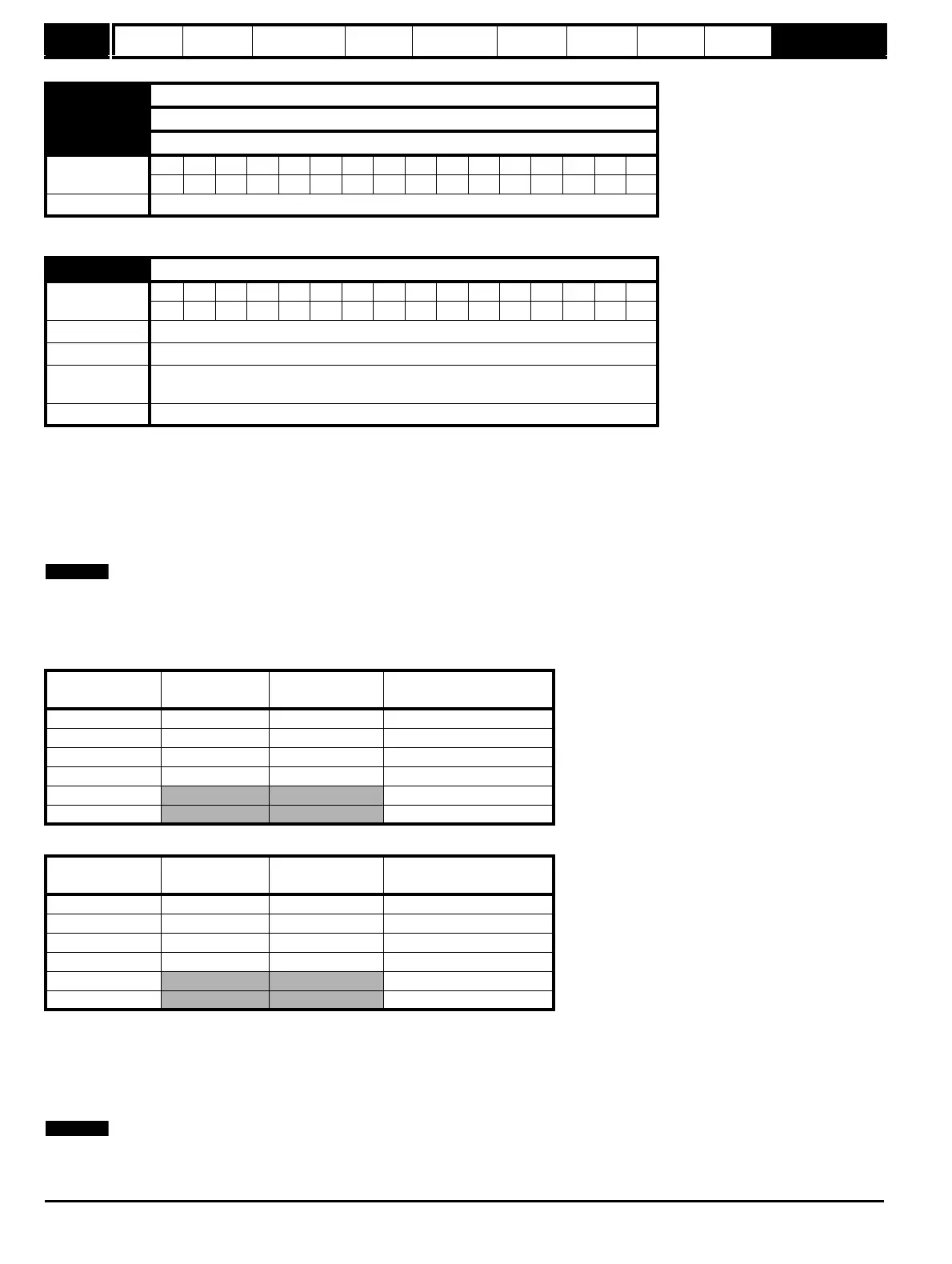
1.14 Reference selector
Coding
Bit SP FI DE Txt VM DP ND RA NC NV PT US RW BU PS
1 111
Range A1.A2(0), A1.Pr(1), A2.Pr(2), Pr(3), PAd(4), Prc(5)
Default A1.A2(0)
Second motor
parameter
Pr 21.03
Update rate 5ms
Pr 1.14
Terminal B4
Destination
Terminal B7
Destination
Pr 1.49
A1.A2(0) Pr 6.29 Pr 1.41 Selected by terminal input
A1.Pr(1) Pr 1.45 Pr 1.46 1
A2.Pr(2) Pr 1.45 Pr 1.46 2
Pr(3) Pr 1.45 Pr 1.46 3
PAd(4)
4
Prc(5)
5
Pr 1.14
Terminal B4
Destination
Terminal B7
Destination
Pr 1.49
A1.A2(0) Pr 6.31 Pr 1.41 Selected by terminal input
A1.Pr(1) Pr 1.45 Pr 1.46 1
A2.Pr(2 Pr 1.45 Pr 1.46 2
Pr(3) Pr 1.45 Pr 1.46 3
PAd(4)
4
Prc(5)
5