Menu 5 Introduction
Parameter
x.00
Parameter
description format
Keypad and
display
Serial
communications
CT Modbus
RTU
PLC Ladder
programming
CTSoft Menu 0
Advanced parameter
descriptions
82 Commander SK Advanced User Guide
www.controltechniques.com Issue Number: 9
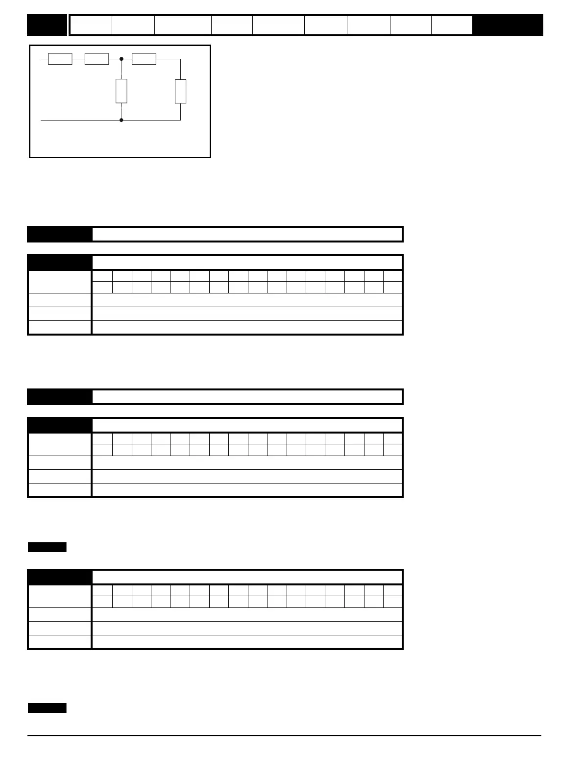
Based on the parameters normally used for the motor equivalent circuit for transient analysis, i.e. L
s
= L
1
+ L
m
, L
r
= L
2
+ L
m
, the transient inductance
is given by:
σL
s
= L
s
- (L
m
2
/ L
r
)
The transient inductance is used as an intermediate variable to calculate the power factor.
0: OFF Slip compensation disabled
1: On Slip compensation enabled
The level of slip compensation is set by the rated frequency and rated speed parameters. Slip compensation is only enabled when this parameter is
set to On(1) and Pr 5.08 is set to a value other than zero or synchronous speed.
Selects the units for the displayed speed.
0: Fr Drive output in Hz (Pr 2.01)
1: SP Motor speed in RPM (Pr 5.04)
2: Cd Machine speed in customer defined units (Scaled from Pr 5.04)
See Parameter scaling Pr 11.21 on page 139 for information on how to scale the rpm (Pr 5.04) when customer defined units is selected.
0: OFF Auto-switching frequency change enabled
1: On Auto-switching frequency change disabled
The drive thermal protection scheme (see Pr 5.18 on page 80) reduces the switching frequency automatically when necessary to prevent the drive
from overheating. It is possible to disable this feature by setting this bit parameter to On(1). If the feature is disabled the drive will trip immediately on
O.ht1 when the IGBT temperature gets too high.
This is only operational with the IGBT junction temperature (Pr 7.34).
5.25 to 5.26 Unused parameters
5.27 Enable slip compensation
Coding
Bit SP FI DE Txt VM DP ND RA NC NV PT US RW BU PS
1 111
Range OFF(0) or On(1)
Default On(1)
Update rate Background
5.28 to 5.33 Unused parameters
5.34 Speed display units {23}
Coding
Bit SP FI DE Txt VM DP ND RA NC NV PT US RW BU PS
1 111
Range Fr(0), SP(1), Cd(2)
Default Fr(0)
Update rate Background
5.35 Disable auto-switching frequency change
Coding
Bit SP FI DE Txt VM DP ND RA NC NV PT US RW BU PS
111
Range OFF(0) or On(1)
Default OFF(0)
Update rate Background
R
1
jwL
1
jwL
2
R
2
/sjwL
m
Steady state per phase equivalent circuit
of an induction motor