Digitax ST Installation Guide 15
Issue: 2 www.controltechniques.com
Safety Information Introduction Mechanical Installation
Electrical Installation
4 Electrical Installation
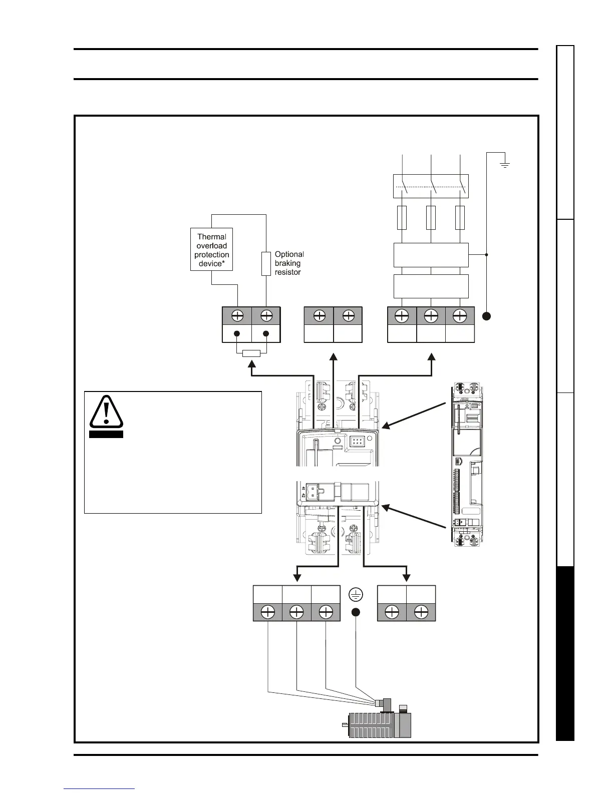
4.1 Power terminal connections
Figure 4-1 Power terminal connections
L1 L2
L2L1
L3/N
UVW
Optional EMC
filter
Optional
line reactor
Fuses
L3/N
Mains
supply
Supply
ground
C
connections
_
+
DC DC
High current
-DC connections
+
_
Low voltage
DC (48V)
*This is not
required if the
optional internal
braking resistor
is used
DST12XX = 200 to 240V 10%
DST14XX = 380 to 480V 10%
±
±
Connectors specification:
Maximum size of power cable
= 4.0mm (10AWG)
Torque setting = 1 N m
2
PE
It is essential that the braking
resistor be protected against
overload caused by a failure of the
brake control. Unless the resistor
has in-built protection, a circuit like
those shown in Figure 4-1 should
be used, where the thermal
protection device disconnects the
AC supply to the drive. Do not use
AC relay contacts directly in series
with the braking resistor circuit,
because it carries DC.
WARNING
 Loading...


