Digitax ST Installation Guide 13
Issue: 2 www.controltechniques.com
Safety Information Introduction
Mechanical Installation
Electrical Installation
3.2 Braking
3.2.1 Optional internal braking resistor
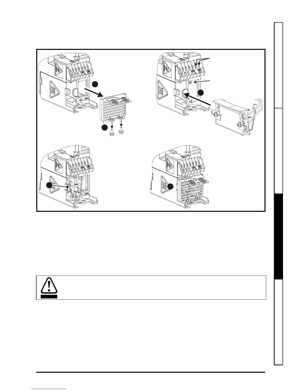
Figure 3-4 Fitting an optional internal braking resistor (top view of drive)
1. Remove screws
2. Remove grill
3. Fit the optional internal braking resistor in the slot provided and electrically connect
the braking resistor (connections shown in Figure 4-1 on page 15)
4. Locate the braking resistor onto the drive tab
5. Refit the grill and mounting screws by reversing the procedure in points 1 and 2
3.2.2 Optional external braking resistor
If using an external braking resistor, the following Warning must be adhered to:
Brake
connections
Thermistor
connector
1
2
3
4
5
Braking resistor: High temperatures and overload protection
Braking resistors can reach high temperatures. Locate braking resistors so that damage
cannot result. Use cable having insulation capable of withstanding the high temperatures.
WARNING
 Loading...


