Digitax ST Installation Guide 27
Issue: 2 www.controltechniques.com
Safety Information Introduction Mechanical Installation
Electrical Installation
4.5 Recommended simple start-up
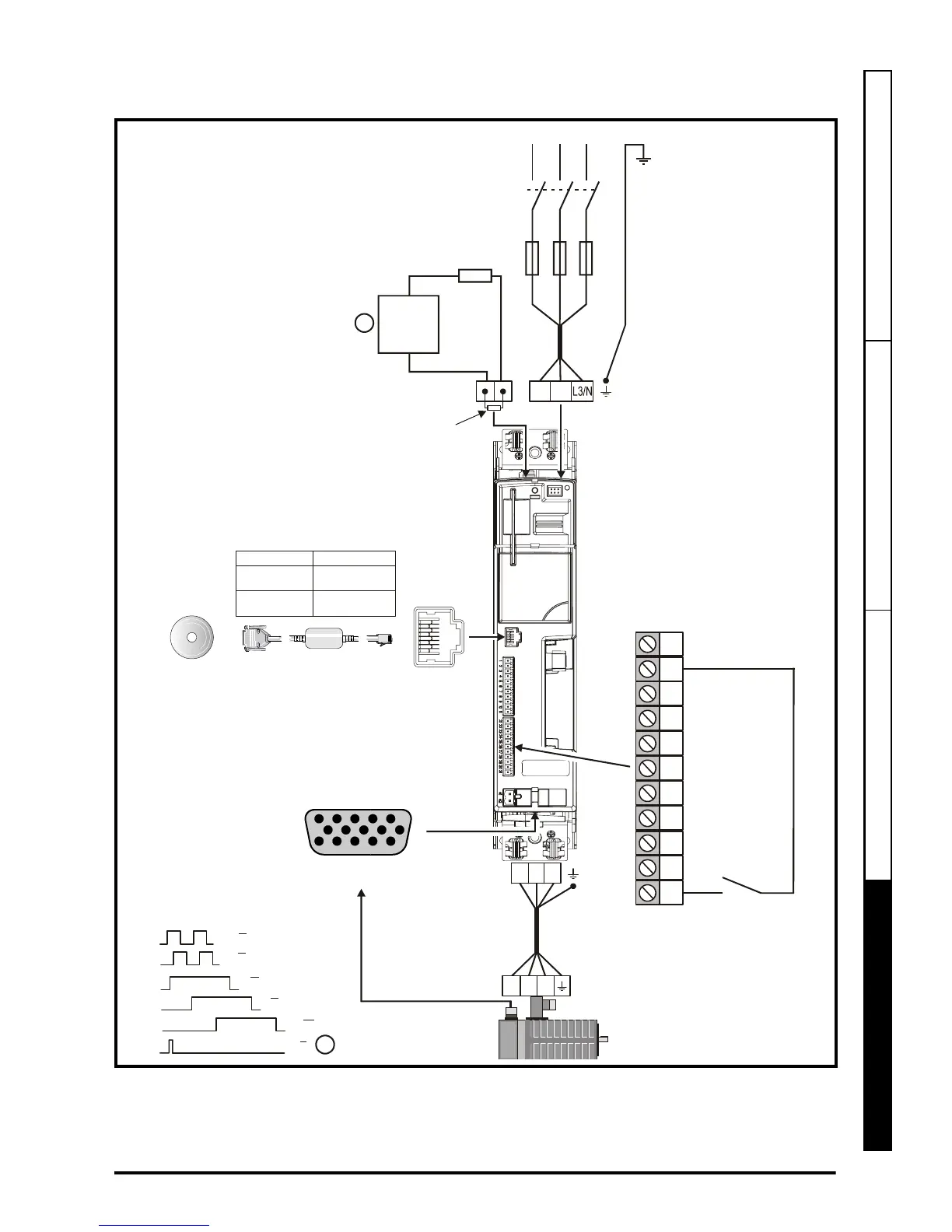
Figure 4-16 Recommended simple start-up via serial communications
1. Marker pulse optional
2. Thermal overload for external braking resistor to protect against fire risk. This must
be wired to interrupt the AC supply in the event of a fault. This is not required if the
optional internal braking thermistor can be connected internally.
U
VW
30
31
28
29
26
27
24
25
23
21
22
Drive
Enable
24V
UVW
A A
B B
U U
V V
W W
Z Z
Encoder connector
15 way D-type
5
10
15
1
6
11
Serial
communications
port
External
braking
resistor
(optional)
L3/NL2
L1
L2
L1
Fuses
Serial Comms
User Interface
Isolated serial
comms lead
DST12XX = 200 to 240V 10%
DST14XX = 380 to 480V 10%
±
±
Part number Description
CT EIA232
Comms cable
CT USB
Comms cable
4500-0087
4500-0096
Internal
braking
resistor
(optional)
Thermal
overload
protection
device
1
2
 Loading...


