Safety
Information
Product
information
Mechanical
installation
Electrical
installation
Getting
started
Basic
parameters
Running the
motor
Optimization
EtherCAT
interface
SMARTCARD
Operation
Onboard
PLC
Advanced
parameters
Technical
Data
Diagnostics
UL listing
information
126 Digitax ST User Guide
Issue Number: 5
**If Ab encoder voltage is greater than 5 V, then the termination resistors
must be disabled Pr 3.39 to 0.
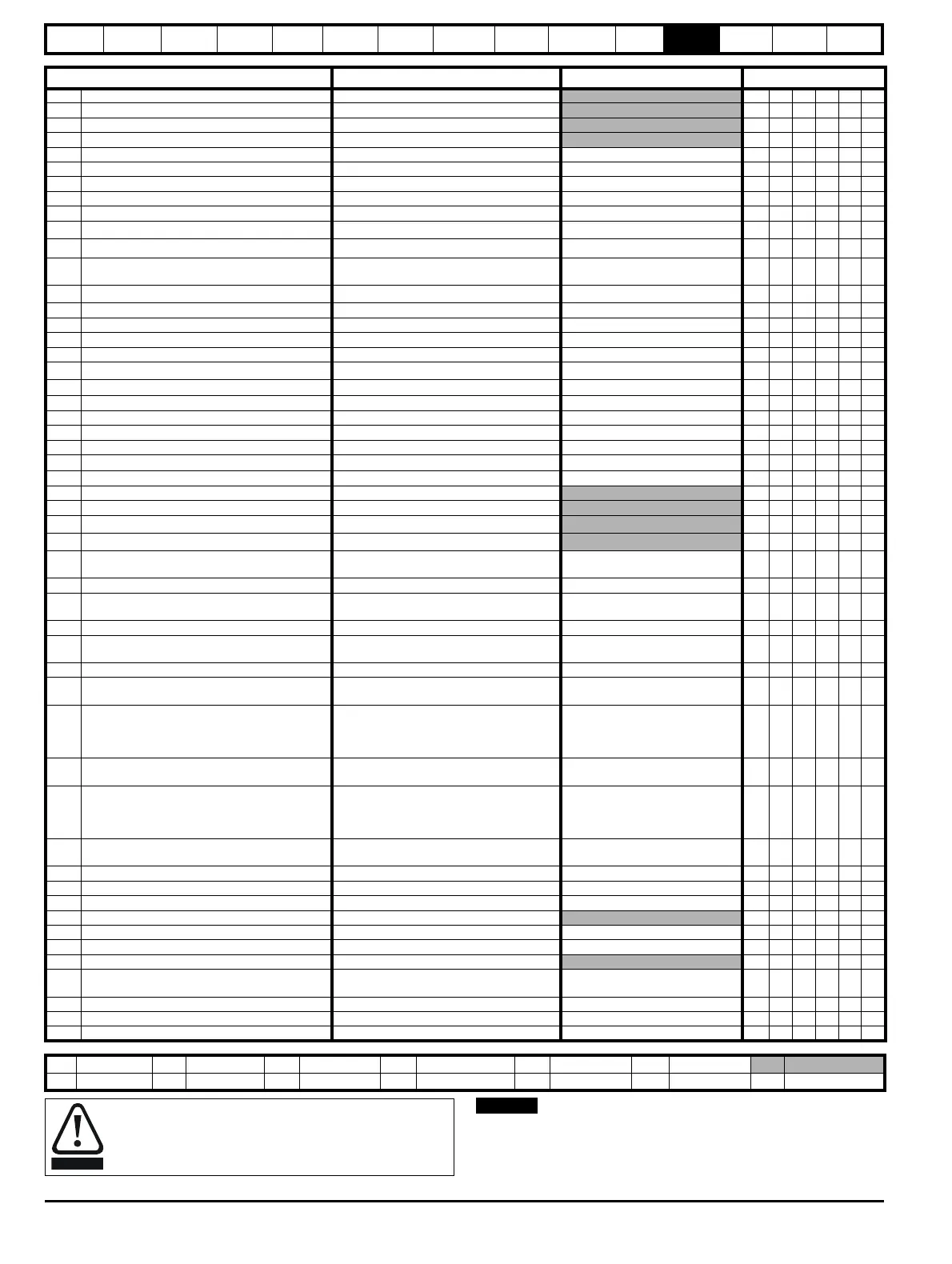
Parameter
Range(
Ú)Default(Ö)
Type
3.01 Final speed reference ±SPEED_MAX rpm RO Bi FI NC PT
3.02 Speed feedback {0.10} ±SPEED_MAX rpm
RO Bi FI NC PT
3.03 Speed error ±SPEED_MAX rpm
RO Bi FI NC PT
3.04 Speed controller output ±TORQUE_PROD_CURRENT_MAX %
RO Bi FI NC PT
3.05 Zero speed threshold 0 to 200 rpm 5 RW Uni US
3.06 At speed lower limit 0 to 40,000 rpm 5 RW Uni US
3.07 At speed upper limit 0 to 40,000 rpm 5 RW Uni US
3.08 Overspeed threshold {0.26} 0 to 40,000 rpm 0 RW Uni US
3.09 Absolute ‘at speed’ detect OFF (0) or On (1) OFF (0) RW Bit US
3.10 Speed controller proportional gain (Kp1) {0.07}
0.0000 to 6.5535 1/rad s
-1
0.0100 RW Uni US
3.11 Speed controller integral gain (Ki1) {0.08}
0.00 to 655.35 s/rad s
-1
1.00 RW Uni US
3.12
Speed controller differential feedback gain
(Kd1)
{0.09}
0.00000 to 0.65535 s
-1
/rad s
-1
0.00000 RW Uni US
3.13 Speed controller proportional gain (Kp2)
0.0000 to 6.5535 1/rad s
-1
0.0100 RW Uni US
3.14 Speed controller integral gain (Ki2) 0.00 to 655.35 1/rad 1.00 RW Uni US
3.15 Speed controller differential feedback gain (Kd2) 0.00000 to 0.65535 s 0.00000 RW Uni US
3.16 Speed controller gain select OFF (0) or On (1) OFF (0) RW Bit US
3.17 Speed controller set-up method 0 to 3 0 RW Uni US
3.18 Motor and load inertia
0.00010 to 90.00000 kg m
2
0.00000 RW Uni US
3.19 Compliance angle
0.0 to 359.9
°
4.0 RW Uni US
3.20 Bandwidth 0 to 255 Hz 10 RW Uni US
3.21 Damping factor 0.0 to 10.0 1.0 RW Uni US
3.22 Hard speed reference ±SPEED_REF_MAX rpm 0.0 RW Bi US
3.23 Hard speed reference selector OFF (0) or On (1) OFF (0) RW Bit US
3.25 Encoder phase angle* {0.43}
0.0 to 359.9
°
0.0 RW Uni US
3.26 Speed feedback selector drv (0), SLot1 (1), SLot2 (2) drv (0) RW Txt US
3.27 Drive encoder speed feedback ±40,000.0 rpm
RO Bi FI NC PT
3.28 Drive encoder revolution counter 0 to 65,535 revolutions
RO Uni FI NC PT
3.29 Drive encoder position {0.11}
0 to 65,535 1/2
16
ths of a revolution
RO Uni FI NC PT
3.30 Drive encoder fine position
0 to 65,535 1/2
32
nds of a revolution
RO Uni FI NC PT
3.31
Drive encoder marker position reset
disable
OFF (0) or On (1) OFF (0) RW Bit US
3.32 Drive encoder marker flag OFF (0) or On (1) OFF (0) RW Bit NC
3.33
Drive encoder turn bits / Linear encoder
comms to sine wave ratio
0 to 255 16 RW Uni US
3.34 Drive encoder lines per revolution {0.27} 0 to 50,000 4096 RW Uni US
3.35
Drive encoder single turn comms bits /
Linear encoder comms bits / Marker mode
0 to 32 bits 0 RW Uni US
3.36 Drive encoder supply voltage** 5 V (0), 8 V (1), 15 V (2) 5V (0) RW Txt US
3.37 Drive encoder comms baud rate
100 (0), 200 (1), 300 (2), 400 (3), 500 (4),
1000 (5), 1500 (6), 2000 (7) kBaud
300 (2) RW Txt US
3.38 Drive encoder type
Ab (0), Fd (1), Fr (2), Ab.SErvo (3),
Fd.SErvo (4), Fr.SErvo (5), SC (6),
SC.Hiper (7), EndAt (8), SC.EndAt (9),
SSI (10), SC.SSI (11)
Ab.SErvo (3) RW Txt US
3.39
Drive encoder termination select / Rotary encoder
select / Comms only encoder mode
0 to 2 1 RW Uni US
3.40 Drive encoder error detection level
Bit 0 (LSB) = Wire break detect
Bit 1 = Phase error detect
Bit 2 (MSB) = SSI power supply bit monitor
Value is binary sum
1RWUniUS
3.41
Drive encoder auto-configuration / SSI
binary format select
OFF (0) or On (1) OFF (0) RW Bit US
3.42 Drive encoder filter 0 (0), 1 (1), 2 (2), 4 (3), 8 (4), 16 (5) ms 0 RW Txt US
3.43 Maximum drive encoder reference 0 to 40,000 rpm 3000 RW Uni US
3.44 Drive encoder reference scaling 0.000 to 4.000 1.000 RW Uni US
3.45 Drive encoder reference ±100.0 %
RO Bi FI NC PT
3.46 Drive encoder reference destination Pr 0.00 to 21.50 Pr 0.00 RW Uni DE PT US
3.47 Re-initialise position feedback OFF (0) or On (1) OFF (0) RW Bit NC
3.48 Position feedback initialised OFF (0) or On (1)
RO Bit NC PT
3.49
Full motor object electronic nameplate
transfer
OFF (0) or On (1) OFF (0) RW Bit US
3.50 Position feedback lock OFF (0) or On (1) OFF (0) RW Bit NC
3.52 Encoder simulation ratio numerator 0.0000 to 1.0000 1.0000 RW Uni US
3.54 Encoder simulation mode 0 to 4 0 RW Uni US
RW Read / Write RO Read only Uni Unipolar Bi Bi-polar Bit Bit parameter Txt Text string
FI Filtered DE Destination NC Not copied RA Rating dependent PT Protected US User save PS Power down save
*Encoder phase angle
The encoder phase angles in Pr
3.25
and Pr
21.20
are copied
to the SMARTCARD when using any of the SMARTCARD
transfer methods.

 Loading...


