Safety
Information
Product
information
Mechanical
installation
Electrical
installation
Getting
started
Basic
parameters
Running the
motor
Optimization
EtherCAT
interface
SMARTCARD
Operation
Onboard
PLC
Advanced
parameters
Technical
Data
Diagnostics
UL listing
information
32 Digitax ST User Guide
Issue: 5
Table 4-16 Connection details for RJ45 connector
The communications port applies a 2 unit load to the communications
network.
Minimum number of connections are 2, 3, 7 and shield. Shielded cable
must be used at all times.
4.12.1 Isolation of the serial communications port
The serial communications port is double insulated and meets the
requirements for SELV in IEC61800-5-1.
An isolated serial communications lead has been designed to connect
the drive to IT equipment (such as lap-top computers), and is available
from the supplier of the drive. See Table 4-17 below for details:
Table 4-17 Isolated serial comms lead details
The “isolated serial communications” lead has reinforced insulation as
defined in IEC60950 for altitudes up to 3,000 m.
N
When using the CT EIA232 Comms cable the available baud rate is
limited to 19.2 k baud.
4.12.2 Multi-drop network
The drive can be used on a 2 wire EIA485 multi-drop network using the
drive's serial communications port when the following guidelines are
adhered to.
Connections
The network should be a daisy chain arrangement and not a star,
although short stubs to the drive are allowed.
The minimum connections are pins 2 (RX TX), 3 (isolated 0V), 7 (RX\
TX\) and the shield.
Pin 4 (+24 V) on each drive can be connected together but there is no
power sharing mechanism between drives and therefore the maximum
power available is the same as a single drive. (If pin 4 is not linked to the
other drives on the network and has an individual load then the
maximum power can be taken from pin 4 of each drive.)
Termination resistors
If a drive is on the end of the network chain then pins 1 and 8 should be
linked together. This will connect an internal 120 Ω termination resistor
between RXTX and RX\TX\. (If the end unit is not a drive or the user
wishes to use their own termination resistor, a 120 Ω termination resistor
should be connected between RXTX and RX\TX\ at the end unit.)
If the host is connected to a single drive then termination resistors
should not be used unless the baud rate is high.
CT Comms Cable
The CT Comms Cable can be used on a multi-drop network but should
only be used occasionally for diagnostic and set up purposes. The
network should be made up entirely of Digitax ST drives.
If the CT Comms Cable is to be used, then pin 6 (TX enable) should be
connected on all drives and pin 4 (+24 V) should be linked to at least 1
drive to supply power to the converter in the cable.
Only one CT Comms Cable can be used on a network.
4.13 Control connections
4.13.1 General
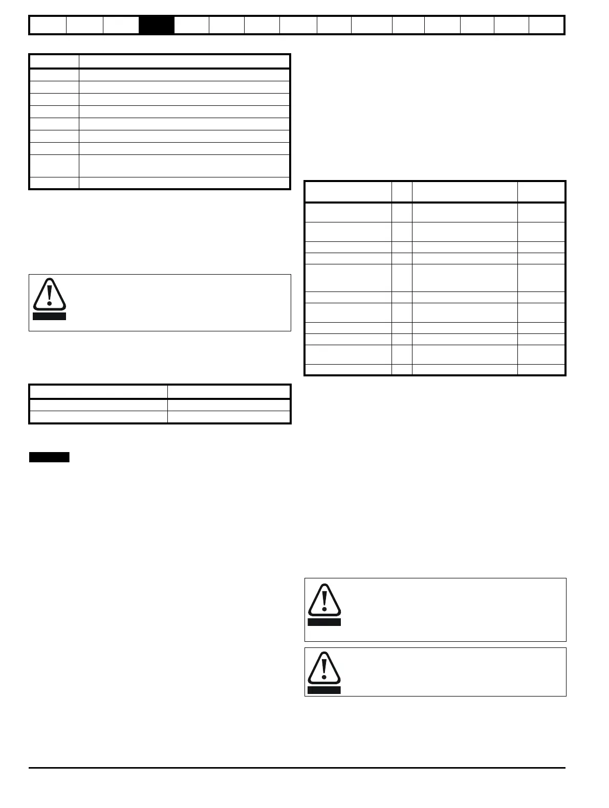
Table 4-18 The control connections consist of:
Key:
All analog terminal functions can be programmed in menu 7.
All digital terminal functions (including the relay) can be programmed in
menu 8.
The setting of Pr 1.14 and Pr 6.04 can cause the function of digital inputs
T25 to T29 to change. For more information, please refer to section
12.22.1 Reference modes on page 166 and section 12.22.7 Start / stop
logic modes on page 170.
Pin Function
1 120 Ω Termination resistor
2RX TX
3 Isolated 0V
4 +24 V (100 mA)
5 Isolated 0V
6 TX enable
7RX\ TX\
8
RX\ TX\ (if termination resistors are required, jumper to
pin 1)
Shield Isolated 0V
In order to meet the requirements for SELV in IEC60950 (IT
equipment) it is necessary for the control computer to be
grounded. Alternatively, when a lap-top or similar device is
used which has no provision for grounding, an isolation
device must be incorporated in the communications lead.
Part number Description
4500-0087 CT EIA232 Comms cable
4500-0096 CT USB Comms cable
Function Qty Control parameters available
Terminal
number
Differential analog input 1
Destination, offset, offset trim,
invert, scaling
5,6
Single ended analog
input
2
Mode, offset, scaling, invert,
destination
7,8
Analog output 2 Source, mode, scaling, 9,10
Digital input 3 Destination, invert, logic select 27, 28, 29
Digital input / output 3
Input / output mode select,
destination / source, invert,
logic select
24, 25, 26
Relay 1 Source, invert 41,42
Drive enable (Safe
Torque Off)
131
+10V User output 1 4
+24V User output 1 Source, invert 22
0V common 6
1, 3, 11, 21,
23, 30
+24V External input 1 2
Destination
parameter:
indicates the parameter which is being controlled by the
terminal / function
Source
parameter:
indicates the parameter being output by the terminal
Mode
parameter:
analog - indicates the mode of operation of the terminal,
i.e. voltage 0-10 V, current 4-20 mA etc.
digital - indicates the mode of operation of the terminal,
i.e. positive / negative logic (the Drive Enable terminal is
fixed in positive logic), open collector.
The control circuits are isolated from the power circuits in the
drive by basic insulation (single insulation) only. The installer
must ensure that the external control circuits are insulated
from human contact by at least one layer of insulation
(supplementary insulation) rated for use at the AC supply
voltage.
If the control circuits are to be connected to other circuits
classified as Safety Extra Low Voltage (SELV) (e.g. to a
personal computer), an additional isolating barrier must be
included in order to maintain the SELV classification.