Safety
Information
Product
information
Mechanical
installation
Electrical
installation
Getting
started
Basic
parameters
Running the
motor
Optimization
EtherCAT
interface
SMARTCARD
Operation
Onboard
PLC
Advanced
parameters
Technical
Data
Diagnostics
UL listing
information
74 Digitax ST User Guide
Issue: 5
9.8.4 Configuring the sync managers
The sync manager is used to control the transmission of CANopen
PDOs over the EtherCAT network.
The following objects 0x1C12 - sync manager 2 PDO assignment
(RxPDO) and 0x1C13 - sync manager 3 PDO assignment (TxPDO) are
required to assign PDOs to the synchronization task. For the purpose of
the example assign one RxPDO to sync manager 2 and two TxPDOs to
sync manager 3.
Figure 9-4 EtherCAT interface sync manager configuration
Assigning RxPDO to the sync manager
To assign RxPDO1 to sync manager 2 PDO assignment set the values
below to the following objects:
• Index: 0x1C12
• Sub index:0x00
•Size: 1
• Value: 1
Setting object 0x1C12, sub-index 0 to a value of 1 (as above) indicates
that one RxPDO will be assigned to the sync manager 2 assignment.
• Index: 0x1C12
• Sub index:0x01
•Size: 2
• Value: 0x1600
Setting object 0x1C12, sub-index 1 to a value of 0x1600 (as above)
maps RxPDO1 to the process data output sync.
Assigning TxPDO to the sync manager
To assign TxPDO1 to sync manager 3 PDO assignment set the values
below to the following objects:
• Index: 0x1C13
• Sub index:0x00
•Size: 1
• Value: 2
Setting object 0x1C13, sub-index 0 to a value of 2 (as above) indicates
that two TxPDOs will be assigned to the sync manager 3 assignment.
• Index: 0x1C13
• Sub index:0x01
•Size: 2
• Value: 0x1A00
• Index: 0x1C13
• Sub index:0x02
•Size: 2
• Value: 0x1A05
Setting object 0x1C13, sub-index 1 to a value of 0x1A00 and sub-index
2 to a value of 0x1A05 (as above) maps TxPDO1 and TxPDO6 to the
process data input sync.
Download the configuration to the master.
After downloading the configuration to the master the LED(s) on the front
of the EtherCAT interface should flash, depending on the port(s)
connected.
Values written to parameters over RxPDOs should now be viewable
using the drive’s keypad so long as the master has put the slave into the
operational state; also, parameter values changed using the drive
keypad will be updated on the master.
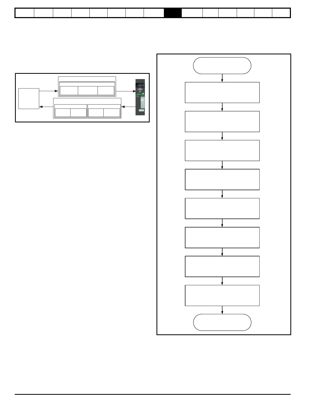
9.9 Quick start flowchart
Figure 9-5 details the steps required to achieve cyclic communications
on the EtherCAT network. This flowchart should be used as the starting
point for all configurations.
Figure 9-5 Quick start flowchart
0x1C12
0x6040
Control word
0x6042
vl_target_velocity
Pr 20.21
RxPDO1
0x1C13
0x6041
Status word
0x6064
position
actual value
TxPDO1
Pr 18.22 Pr 20.22
TxPDO6
PLC
Ensure the Control Techniques .xml file is in
the appropriate folder on the hard drive of the
master
Check the LED status of the SM-EtherCAT
module
In the master,
scan the EtherCAT network
Configure the PDOs with the mappings
required
Check the front of the SM-EtherCAT module
to ensure that the LED relating to the
connection being used is flashing, this
confirms that communications are functioning
Download or activate the configuration to the
master
Configure the Sync managers using the
required PDOs
END
START
 Loading...


