Safety
Information
Product
information
Mechanical
installation
Electrical
installation
Getting
started
Basic
parameters
Running the
motor
Optimization
EtherCAT
interface
SMARTCARD
Operation
Onboard
PLC
Advanced
parameters
Technical
Data
Diagnostics
UL listing
information
170 Digitax ST User Guide
Issue Number: 5
is carried out. If σL
s
cannot be measured it can be calculated from
the steady state per-phase equivalent circuit of the motor as follows:
I
fs
is the peak full scale current feedback = K
C
x √2 / 0.45. Where K
C
is defined in Pr 11.32.
V
fs
is the maximum DC bus voltage.
Therefore:
Pr 4.13 = Kp = (L / 167 μs) x (K
C
x √2 / 0.45 / V
fs
) x (256 / 5)
= K x L x K
C
Where:
K = [√2 / (0.45 x V
fs
x 167μs)] x (256 / 5)
This set-up will give a step response with minimum overshoot after a
step change of current reference. The approximate performance of the
current controllers will be as given below. The proportional gain can be
increased by a factor of 1.5 giving a similar increase in bandwidth,
however, this gives at step response with approximately 12.5 %
overshoot.
The integral gain (Pr 4.14) is less critical and should be set so that
Pr 4.14 = Ki = Kp x 256 x T /
τ
m
Where:
τ
m
is the motor filter (L / R).
R is the per phase stator resistance of the motor (i.e. half the
resistance measured between two phases).
Therefore
Pr 4.14 = Ki = (K x L x K
C
) x 256 x 167μs x R / L
= 0.0427 x K x R x K
C
The above equation gives a conservative value of integral gain. In some
applications where it is necessary for the reference frame used by the
drive to dynamically follow the flux very closely (i.e. high speed closed-
loop induction motor applications) the integral gain may need to have a
significantly higher value.
12.22.7 Start / stop logic modes
This parameter is provided to allow the user to select several predefined
digital input routing macros to control the sequencer. When a value
between 0 and 3 is selected the drive processor continuously updates
the destination parameters for digital I/O T25, T26 and T27, and the
enable sequencer latching bit (Pr 6.40). When a value of 4 is selected
the destination parameters for these digital I/O and Pr 6.40 can be
modified by the user.
If Pr 6.04 is changed then a drive reset is required before the function of
T25, T26 or T27 will become active.
If Pr 6.04 has been set to a value of 0 to 3, then setting Pr 6.04 to 4 does
not automatically reconfigure terminals T25, T26 and T27 to their default
functions. To return terminals T25, T26 and T27 to their default
functions, one of the following operations should be performed.
• Drive defaults should be restored. See section 5.6.6 Restoring
parameter defaults on page 46 for details.
• Manually set Pr 6.04 to 4, Pr 6.40 to 0, Pr 8.22 to 10.33, Pr 8.23 to
6.30, and Pr 8.24 to 6.32.
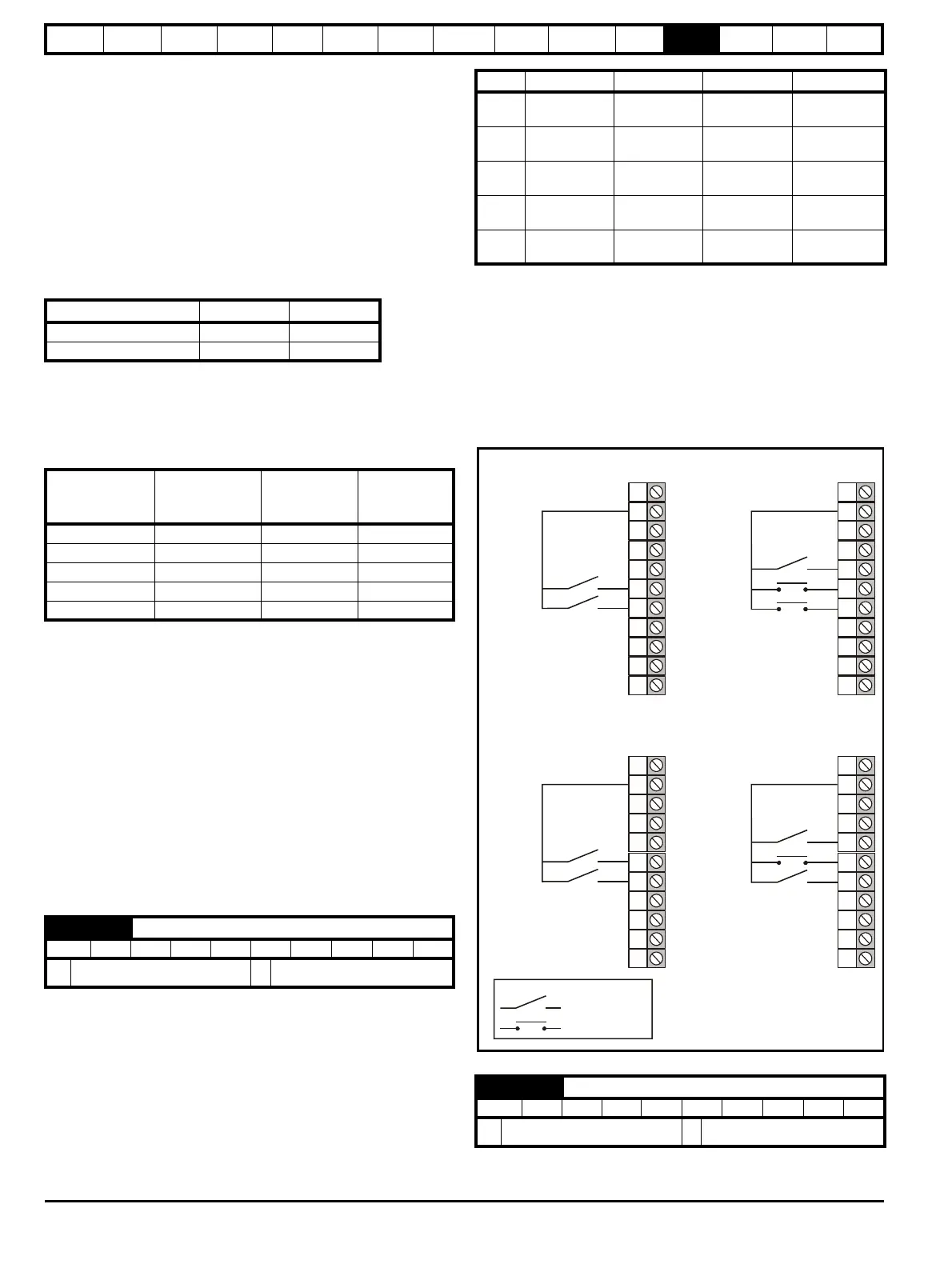
Figure 12-18 Digital input connections when Pr 6.04 is set
to 0 to 3
Drive voltage rating Vfs K
200 V 415V 2322
400 V 830V 1161
Switching
frequency
kHz
Current control
sample time
μs
Gain
bandwidth
Hz
Phase
delay
μs
3 167 TBA 1160
4 125 TBA 875
683TBA581
8 125 TBA 625
12 83 TBA 415
6.04 Start / stop logic select
RW Uni US
Ú
0 to 4
Ö
0
σL
s
L
s
L
m
2
L
r
----------
⎝⎠
⎜⎟
⎛⎞
–=
Pr 6.04 T25 (Pr 8.22) T26 (Pr 8.23) T27 (Pr 8.24) Pr 6.40
0
Pr 6.29
(Fast Disable)
Pr 6.30
(Run Forward)
Pr 6.32
(Run Reverse)
0
(Non Latching)
1
Pr 6.39
(Run Permit)
Pr 6.30
(Run Forward)
Pr 6.32
(Run Reverse)
1
(Latching)
2
Pr 6.29
(Fast Disable)
Pr 6.34
(Run)
Pr 6.33
(Fwd/Rev)
0
(Non Latching)
3
Pr 6.39
(Run Permit)
Pr 6.34
(Run)
Pr 6.33
(Fwd/Rev)
1
(Latching)
4
User
programmable
User
programmable
User
programmable
User
programmable
6.40 Enable sequencer latching
RW Bit US
Ú
OFF (0) or On (1)
Ö
OFF (0)
30
31
28
29
26
27
24
25
23
21
22
+24V
Run Fwd
Run Rev
Pr 6.04 is set to 0
30
31
28
29
+24V
Run
Fwd/Rev
Pr 6.04 is set to 2

 Loading...


