What to do if my Emerson Servo Drive shows Motor Overtemp?
- JJohn SmithAug 20, 2025
If your Emerson Servo Drive displays a 'Motor Overtemp' error, allow the motor to cool down. Then, use the Reset Button or Input Line to clear the fault.

What to do if my Emerson Servo Drive shows Motor Overtemp?
If your Emerson Servo Drive displays a 'Motor Overtemp' error, allow the motor to cool down. Then, use the Reset Button or Input Line to clear the fault.
What to do if my Emerson Servo Drive shows Drive Overtemp?
If your Emerson Servo Drive displays a 'Drive Overtemp' error, allow the drive to cool down and then cycle logic power.
What to do if my Emerson Servo Drive shows Overspeed?
If your Emerson Servo Drive displays an 'Overspeed' error, use the Reset Button or Input Line.
What to do if my Emerson Servo Drive displays High DC Bus error?
If your Emerson Servo Drive displays a 'High DC Bus' error, use the Reset Button or Input Line.
What to do if my Emerson Servo Drive displays Low DC Bus error?
If your Emerson Servo Drive displays a 'Low DC Bus' error, use the Reset Button or Input Line.
What to do if my Emerson Servo Drive displays Following Error (Pulse mode only)?
If your Emerson Servo Drive displays a 'Following Error (Pulse mode only)', use the Reset Button or Input Line.
What to do if my Emerson Servo Drive displays RMS Shunt Power error?
If your Emerson Servo Drive displays a 'RMS Shunt Power' error, use the Reset Button or Input Line.
What to do if my Emerson Servo Drive displays Power Module error?
If your Emerson Servo Drive displays a 'Power Module' error, use the Reset Button or Input Line.
What to do if my Emerson Servo Drive displays Invalid Configuration?
If your Emerson Servo Drive displays an 'Invalid Configuration' error, use the Reset Button or Input Line.
What to do if my Emerson Servo Drive displays NVM Invalid error?
If your Emerson Servo Drive displays a 'NVM Invalid' error, use the Reset Button or Input Line.
| Product Type | Servo Drive |
|---|---|
| Model | Epsilon EP Drive 400518-01 |
| Manufacturer | Emerson |
| Input Frequency | 50/60 Hz |
| Output Power | 1.5 kW |
| Humidity | 5% to 95% non-condensing |
| Mounting | Panel Mount |
| Feedback Type | Resolver |
| Protection Features | Overcurrent, Overvoltage, Undervoltage, Overtemperature |
| Operating Temperature | 0°C to 55°C |
| Input Voltage | 200-240V AC |
| Communication Interface | Ethernet/IP, Modbus TCP |
General safety rules and warnings for proper installation and operation.
Defines personnel qualified to install, operate, and maintain the drive.
Requirements for mounting the drive in an enclosure for protection.
Emphasizes careful consideration of drive settings for safe operation.
Compliance with EU Machinery Directive and safety-critical applications.
Identifies markings used for safety-related information in the manual.
Procedure for safely disconnecting power from the drive before servicing.
Hazard warning for plug-and-socket connections and safety measures.
Importance of proper grounding for safety and compliance with regulations.
Requirement for over-current protection at the AC power input.
Ensuring isolation of external control circuits from human contact.
Information regarding UL listing and conditions of acceptability for the drive.
Details on built-in motor overload protection and its operation.
Statement of conformity to EU safety and EMC standards.
Description of the stand-alone, fully digital, brushless servo drive and its capabilities.
Essential precautions for safe startup, grounding, and emergency stops.
Guidance for meeting EMC requirements through proper installation and shielding.
Methods to improve noise immunity and reduce emissions via low impedance connections.
Precautions to prevent drive damage or malfunction from static discharge.
Guidelines for operating the drive in different environmental conditions.
Important notes on routing high/low power lines and grounding for EMC.
Diagram showing typical panel layout for AC filter and cable connections.
Method for grounding shielded cables to the enclosure for EMC compliance.
Information on necessary AC line filters for EMC compliance and recommended models.
Instructions and dimensions for physically mounting the drive.
Detailed guidance on making high power electrical connections to the drive.
Detailed guidance on system grounding for safe and quiet electrical installations.
Specifies voltage range, phase, and grounding requirements for AC power input.
Diagrams showing direct AC supply connections for specific transformer configurations.
Diagrams and guidelines for using isolation transformers for AC power supply.
Guidance and tables for sizing the KVA rating of required transformers.
Specifies required fuses, circuit breakers, and wire gauges for AC power connections.
Details on making AC power connections, including safety precautions.
Information on operating the drive with a DC input supply.
Instructions for installing external shunt resistors for regen energy dissipation.
Guidelines for connecting motor power cables, including length and connector types.
Specific wiring details for NT and MG motor types.
Wiring diagrams for XV 40-80mm and XV 130mm motors.
Instructions for connecting the DC logic power supply to the drive.
Details on connecting motor feedback using the 15-pin D connector.
Details for connecting encoder quadrature, marker, and commutation signals.
Wiring instructions for the motor overtemp circuit.
Wiring diagrams for motor brake connections for different motor types.
Explanation of input/output configurations and drive enable function.
Pinout and functions of the 26-pin I/O connector.
How the drive's diagnostic display shows status and fault codes.
Table and explanation of different status codes displayed on the drive.
Lists fault codes, their priority, and general reset information.
Detailed explanations for specific fault codes like Flash Invalid and Power Up Test.
Information on the Active Drive Faults dialog box and fault reset options.
Procedures for resetting different types of drive faults.
How to view currently active drive faults using software.
Methods to reboot the drive, such as cycling power.
Overview of available optional accessories for the Epsilon EP drive.
Details on the STI-24IO interface board for digital I/O signals.
Details on the STI-SNCOA interface board for analog/sync signals.
Details on the STI-SNCI interface board for sync input signals.
Details on the STI-ENC interface board for encoder feedback signals.
Comprehensive technical specifications for the Epsilon EP Series drives.
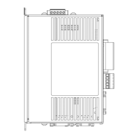
Mechanical dimensions and panel width requirements for Epsilon EP drives.
Wiring diagrams for various Epsilon EP interface and motor cables.
Wiring diagrams for XV motor cables (XTMDS-XXX).
Wiring diagrams for XCMDS-XXX motor cables.
Wiring diagrams for XCMDBS-XXX motor cables.
Wiring diagrams for XTBMS-XXX motor brake cables.
Wiring diagrams for XEFTS-XXX encoder feedback cables.
Wiring diagrams for XEFCS-XXX encoder feedback cables.
Wiring diagrams for NT and MG motor cables (CMDS-XXX, CMMS-XXX).
Wiring diagrams for CBMS-XXX motor brake cables.
Wiring diagrams for SNCDD-915-XXX and SNCFLOA-XXX sync cables.
Wiring diagrams for SNCMD-815-XXX sync cables.
Wiring diagrams for SNCMD-89-XXX sync cables.
Wiring diagrams for ESA-SP-485-XXX and ETH-PATCH-XXX communication cables.


