Description
Physical description
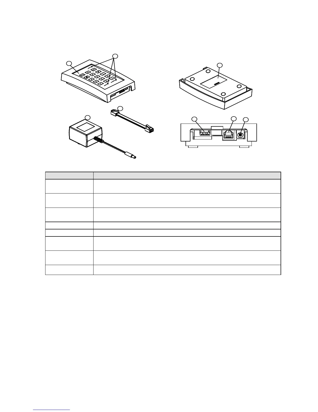
Figure 1 identifies the parts of the FA-700.
Figure 1: FA-700 Parts List
Table 1: FA-700 Parts and Purpose
Used to enter the call-to phone number, activate a phone test, and cancel
an alarm.
Power, Program, and Alarm present operational status of the FA-700.
LEDs do not function when operating on backup battery power.
Accommodates two AA batteries for backup power during an AC power
failure.
These switches dictate how the FA-700 will respond to alarm conditions.
RJ-11 phone jack is used to connect the FA-700 to a standard phone line.
Connects to the AC power adapter to provide 6 volts DC power to operate
the FA-700.
Converts AC power to 6 volts DC power to operate the FA-700.
Connects the FA-700 to the wall phone jack, length 7ft (2.1m).
General description
The FA-700 monitors your home for a variety of alarm conditions. When an alarm event
occurs, the FA-700 calls the programmed phone number for the following alarms:
• Temperature drops below 45ºF (7ºC) or rises above 85ºF (34ºC) (DIP switch selectable)
• FA-700 low battery condition (backup AA batteries)
When a problem occurs at the monitored location, the FA-700 will start calling the
programmed phone number over a standard phone line and describe (in English) the current
alarm(s). The FA-700 will continue calling until the alarm call-out is canceled.
LEDs
The FA-700 has three LEDs: Power, Program, and Alarm located on its front panel. These
LEDs present operating status of the FA-700. Table 2 explains the operational states of the
three LEDs.