EasyManua.ls Logo

Emerson Fisher FIELDVUE DVC6000 HW2 User Manual

Emerson Fisher FIELDVUE DVC6000 HW2
120 pages
To Next Page IconTo Next Page
Page #1 background imageLoading...
Page #1 background image
www.Fisher.com
Fisher
FIELDVUE
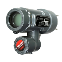
DVC6000 HW2 Digital Valve
Controller
This manual applies to
Instrument Level HC, AD, PD, ODV
Device Type 130b
Device Revision 1 & 2
Hardware Revision 2
Firmware Revision 6
DD Revision 4 & 5
Contents
Section 1 Introduction 3.................
Scope of Manual 3..............................
Conventions Used in this Manual 3................
Description 3..................................
Specifications 4................................
Related Documents 7...........................
Educational Services 8...........................
Section 2 Wiring Practices 9..............
Control System Requirements 9..................
HART Filter 9.................................
Voltage Available 9............................
Compliance Voltage 11........................
Auxiliary Terminal Wiring Length Guidelines 12....
Maximum Cable Capacitance 12.................
Installation in Conjunction with a Rosemountt
333 HART Tri‐Loopt HART‐to‐Analog
Signal Converter 17.........................
Section 3 Configuration 19...............
Guided Setup 19...............................
Manual Setup 19...............................
Mode and Protection 20........................
Instrument Mode 20.......................
Write Protection 20........................
Instrument 20................................
Identification 20...........................
Serial Numbers 21.........................
Units 21..................................
Terminal Box 21...........................
Input Range 21............................
Spec Sheet 22.............................
Edit Instrument Time 22....................
Travel/Pressure Control 22......................
Travel/Pressure Select 22...................
Cutoffs and Limits 23.......................
End Point Pressure Control 23................
Pressure Control 24........................
Pressure Fallback 24........................
Control Mode 25..........................
Characterization 25........................
Dynamic Response 27......................
Tuning 28....................................
Travel Tuning 28...........................
Pressure Tuning 31........................
Travel/Pressure Integral Settings 31..........
Valve and Actuator 32..........................
Partial Stroke Test 34..........................
Outputs 37...................................
Output Terminal Configuration 37............
Switch Configuration 37....................
HART Variable Assignments 38..............
Transmitter Output 38.....................
Burst Mode 38............................
Alert Setup 39.................................
Change to HART 5 / HART 7 40....................
Instruction Manual
D103785X012
DVC6000 HW2 Digital Valve Controller
June 2017

Table of Contents

Questions and Answers:

Emerson Fisher FIELDVUE DVC6000 HW2 Specifications

General IconGeneral
ManufacturerEmerson
Product TypeDigital Valve Controller
SeriesFIELDVUE
Hardware RevisionHW2
Input Signal4-20 mA
Output Signal4-20 mA
Temperature Range-40 to 85°C (-40 to 185°F)
Enclosure RatingNEMA 4X, IP66
Communication ProtocolHART
Power Supply24 VDC
MountingDirect Mounting

Summary

Section 1 Introduction

Installation, Pneumatic and Electrical Connections, and Initial Configuration

Basic installation, pneumatic, and electrical connection guidance.

Section 1 Introduction (continued)

Specifications

Details product specifications, including capabilities and compatibility.

Electrical Classification

Lists hazardous area approvals including CSA, FM, ATEX, and IECEx.

Communication Protocol

Specifies supported communication protocols, HART 5 or HART 7.

Actuator Compatibility

Lists stem travel and shaft rotation compatibility for actuators.

Section 2 Wiring Practices

Voltage Available

States the minimum voltage requirement for the digital valve controller.

Section 2 Wiring Practices (continued)

Remote Travel Sensor Connections

Describes connection options for remote travel sensors.

Using a Potentiometer with Two Fixed Resistors as a Remote Travel Sensor

Explains how to connect a potentiometer with two fixed resistors for travel feedback.

Commissioning the Digital Valve Controller for use with the HART Tri-Loop Signal Converter

Details preparing the controller for HART Tri-Loop communication.

Using an External 10 kOhm External Potentiometer as a Remote Travel Sensor

Details how to connect an external 10 kOhm potentiometer for travel feedback.

Section 3 Configuration

Guided Setup

Guides the user through the initial instrument setup process.

Manual Setup

Allows manual configuration of controller parameters for application.

Section 3 Configuration (continued)

Mode and Protection

Configures instrument operating modes and write protection settings.

Cutoffs and Limits

Sets high and low limits or cutoffs for travel and pressure.

Pressure Control

Configures pressure range high and low values for pressure control.

Control Mode

Displays and configures the instrument's control mode (Analog/Digital).

Dynamic Response

Adjusts valve response rates and setpoint filter time.

End Point Pressure Control (EPPC)

Enables End Point Pressure Control to manage output at travel extremes.

Pressure Fallback

Configures parameters for fallback to pressure control upon travel sensor issues.

Characterization

Defines the relationship between input signal and valve travel.

Travel/Pressure Control

Configures the instrument's control mode and fallback behavior.

Tuning

Travel Tuning

Selects pre-defined or custom tuning sets for valve travel control.

Travel Tuning Set

Chooses from eleven pre-selected tuning sets for travel tuning.

Tuning (continued)

Performance Tuner

Optimizes controller tuning by performing a step response test.

Pressure Tuning

Selects pre-defined or custom tuning sets for pressure control.

Valve and Actuator

Configures valve style, actuator style, and feedback connections.

Partial Stroke Test (PST) (Instrument Level ODV only)

Guides the user through running a Partial Stroke Test for valve diagnostics.

Stabilize/Optimize

Adjusts valve response by changing digital valve controller tuning.

Outputs

Outputs (continued)

Alert Setup

Change to HART 5 / Change to HART 7

Section 4 Calibration

Calibration Overview

Provides an overview of calibration procedures for the instrument.

Section 4 Calibration (continued)

Travel Calibration

Calibrates the travel sensor and valve assembly.

Manual Calibration

Allows manual calibration of valve travel using analog or digital adjustment.

Auto Calibration

Guides through automatic calibration of travel, crossover, and sensor adjustments.

Sensor Calibration

Pressure Sensors

Calibrates pressure sensors for accurate readings.

Sensor Calibration (continued)

Supply Pressure Sensor

Calibrates the supply pressure sensor (not available for HC level).

Travel Sensor

Guides adjustment of the travel sensor if replaced or misadjusted.

Travel Sensor (continued)

DVC6015 and DVC6035 Remote Feedback Units

Provides instructions for adjusting the travel sensor on DVC6015/DVC6035 units.

DVC6025 Remote Feedback Unit

Details adjustments for the travel sensor on DVC6025 units.

Analog Input Calibration

Calibrates the analog input sensor to accurately read current signals.

Analog Input Calibration (continued)

Relay Adjustment

Adjusts the relay for proper valve positioning.

Relay Adjustment (continued)

PST Calibration (ODV Instrument Level only)

Section 5 Device Information, Diagnostics, and Alerts

Section 5 Device Information, Diagnostics, and Alerts (continued)

Diagnostics

Provides tools for diagnosing valve and instrument performance.

Partial Stroke Test

Performs a partial stroke test to verify valve operation.

Section 6 Maintenance and Troubleshooting

Personal injury or property damage... (Safety Warning Group)

General safety warnings regarding cover failure and overpressure.

To avoid static discharge... (Safety Warning Group)

Safety precautions for cleaning plastic covers to prevent sparks.

Avoid personal injury or property damage... (Safety Warning Group)

Critical safety warnings before performing maintenance procedures.

Section 6 Maintenance and Troubleshooting (continued)

Module Base Maintenance

Describes maintenance procedures for the module base assembly.

Replacing the Module Base

Details the procedure for installing a new module base assembly.

Submodule Maintenance

Outlines maintenance for I/P converter, PWB, and pneumatic relay submodules.

Removing the Module Base

Provides steps for safely removing the module base assembly.

Replacing the I/P Filter (continued)

Replacing the I/P Converter (continued)

Removing the Terminal Box (continued)

Travel Sensor

Explains the process of replacing the travel sensor assembly.

Assembly (continued)

Travel Sensor Adjustment with a Multimeter (DVC6015)

Provides steps for adjusting the DVC6015 travel sensor using a multimeter.

DVC6025 Feedback Unit (continued)

Travel Sensor Adjustment with a Multimeter (DVC6025)

Provides steps for adjusting the DVC6025 travel sensor using a multimeter.

DVC6035 Remote Feedback Unit (continued)

Travel Sensor Adjustment with a Multimeter (DVC6035)

Provides steps for adjusting the DVC6035 travel sensor using a multimeter.

Troubleshooting

Checking Voltage Available

Describes how to test voltage availability at the instrument.

Troubleshooting (continued)

DVC6000 HW2 Troubleshooting Checklist

A checklist to help diagnose instrument issues.

Section 7 Parts

Section 7 Parts (continued)

Parts List (continued)

Related product manuals