Installation
December 2009
2-13
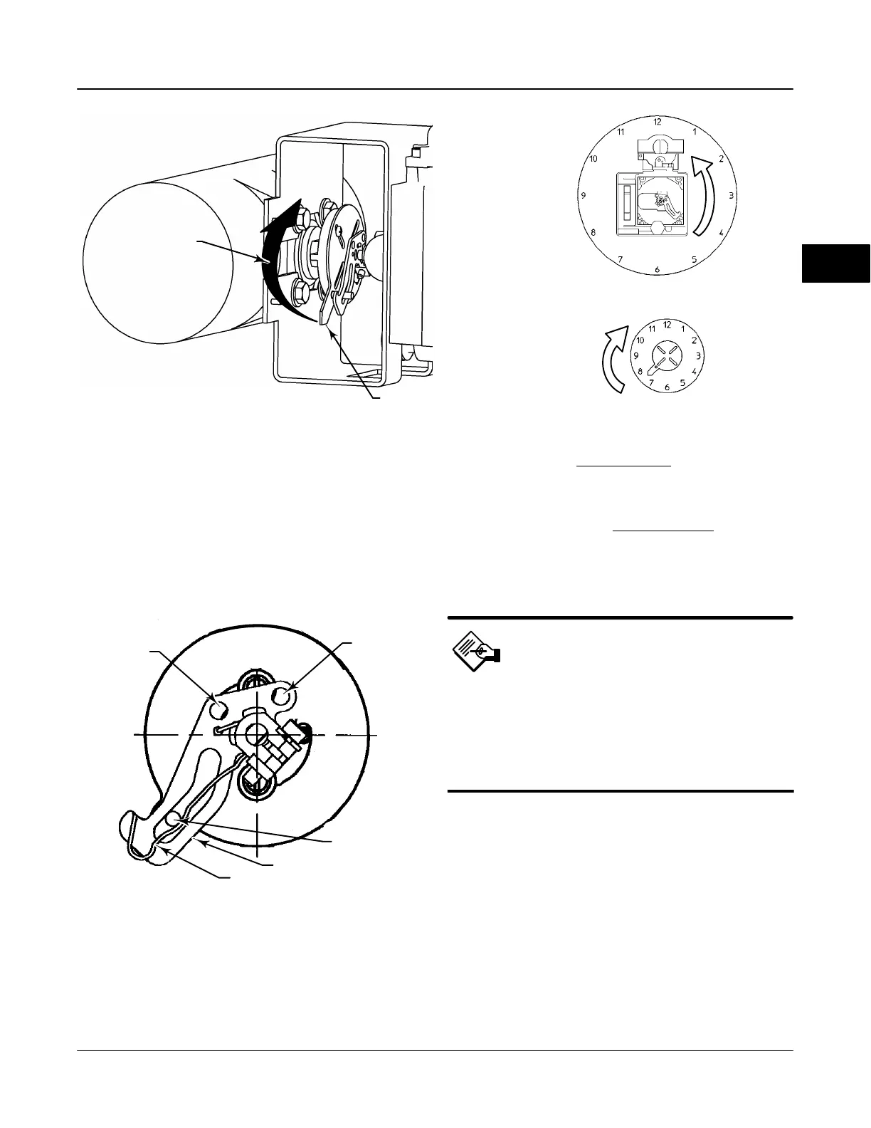
Figure 2-10. Explanation of FIELDVUE DVC6030f Travel Indicator Starting Position and Movement if Counterclockwise Orientation is
Selected for “Travel Sensor Motion” in ValveLink Software or the Field Communicator
19B3879-A / DOC-2
STARTING POSITION OF THE TRAVEL INDICATOR
ASSEMBLY IF INCREASING PRESSURE FROM
OUTPUT A DRIVES THE INDICATOR CLOCKWISE
THE POTENTIOMETER SHAFT WILL ROTATE
COUNTERCLOCKWISE AS VIEWED FROM THE
BACK OF THE FIELDVUE INSTRUMENT.
STARTING POSITION OF
TRAVEL INDICATOR ASSEMBLY
(DIGITAL VALVE CONTROLLER
OUTPUT A AT 0 PSI).
MOVEMENT OF TRAVEL
INDICATOR ASSEMBLY WITH
INCREASING PRESSURE FROM
OUTPUT A.
IN THIS POSITION, THE “A” HOLE
IN THE FEEDBACK ARM WILL BE
ALIGNED WITH THE REFERENCE
HOLE IN THE DIGITAL VALVE
CONTROLLERS HOUSING.
DVC6030f FEEDBACK
ARM MOVEMENT
ACTUATOR SHAFT MOVEMENT
E0989
NOTE: DVC6030f TRAVEL COUNTS (COUNTERCLOCKWISE) = 3100 $ 700
Figure 2-11. Positioning Travel Indicator Pin in the Feedback
Arm (Viewed as if Looking from the FIELDVUE DVC6030f
toward the Actuator)
FEEDBACK ARM
BIAS SPRING
TRAVEL
INDICATOR PIN
48B4164-B / DOC
HOLE A
HOLE B
Note
ValveLink software and the Field
Communicator use the convention of
clockwise (figure 2-9) and
counterclockwise (figure 2-10) when
viewing the potentiometer shaft from
the back of the FIELDVUE instrument.
5. Attach the travel indicator to the shaft connector or
spacer as described in the mounting kit instructions.
6. Attach the mounting bracket to the digital valve
controller.
7. Position the digital valve controller so that the pin
on the travel indicator engages the slot in the feedback
arm and that the bias spring loads the pin as shown in
figure 2-11. Attach the digital valve controller to the
actuator or positioner plate.
8. If a travel indicator scale is included in the
mounting kit attach the scale as described in the
mounting kit instructions.
2

 Loading...


