Installation
December 2009
2-25
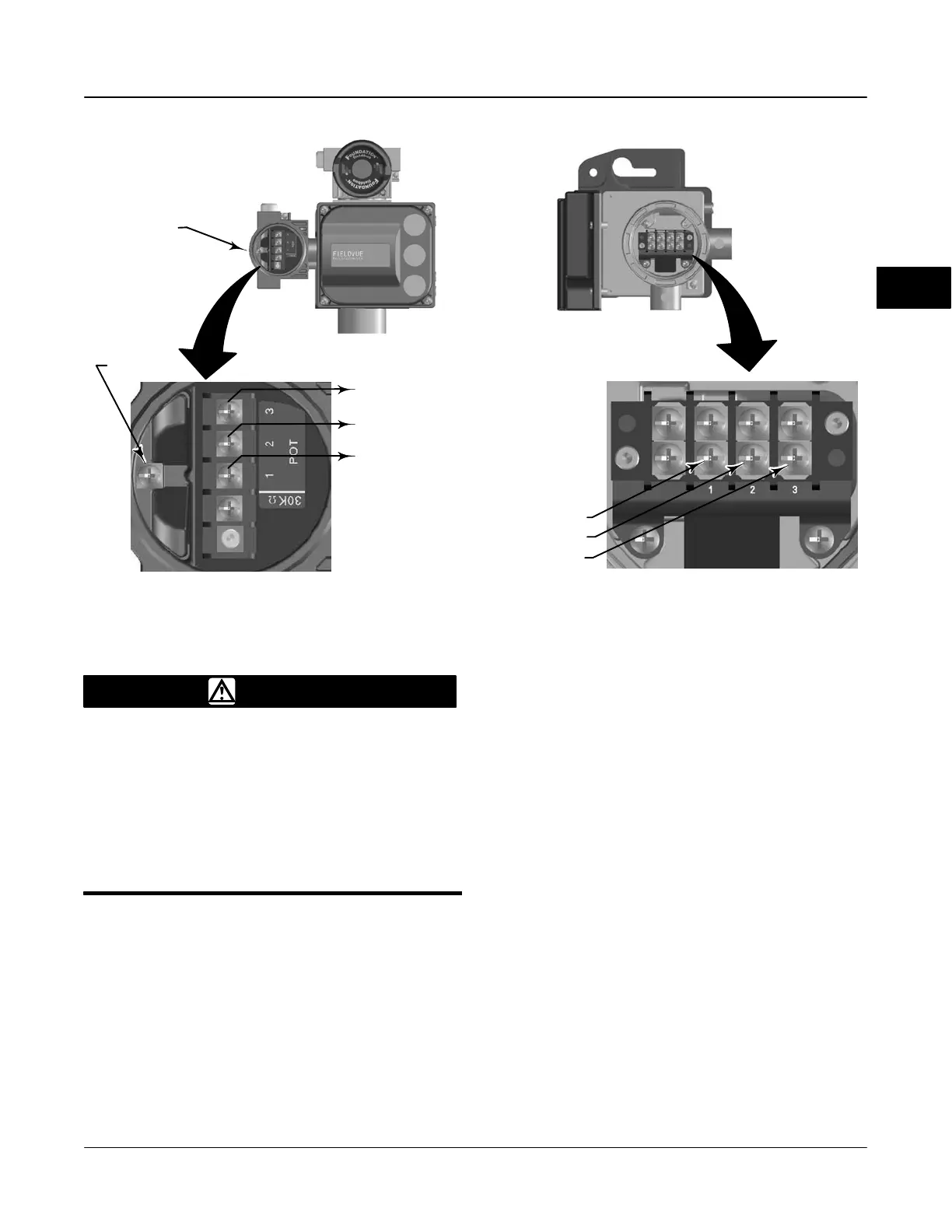
FEEDBACK CONNECTIONS TERMINAL BOX
FEEDBACK UNIT
TO FEEDBACK UNIT TERMINAL 3
TO FEEDBACK UNIT TERMINAL 2
TO FEEDBACK UNIT TERMINAL 1
GROUND
SCREW
TERMINAL 1
TERMINAL 3
TERMINAL 2
W8478-1 / IL
W8475-FF / IL
W8477 / IL
W8476 / IL
BASE UNIT
FEEDBACK UNIT
FEEDBACK CONNECTIONS
TERMINAL BOX
Figure 2-21. Terminal Details for Connecting Base Unit and Feedback Units of Remote-Mounted Digital Valve Controllers
WARNING
Personal injury or property damage,
caused by wiring failure, can result if
the feedback wiring connecting the
base unit with the remote feedback
unit shares a conduit with any other
power or signal wiring.
Do not place feedback wiring in the
same conduit as other power or
signal wiring.
Using the DVC6015, DVC6025 & DVC6035
Feedback Unit as a Remote Travel Sensor
The feedback unit mounts on the actuator and is
connected to the base unit, mounted on a pipestand or
wall, with a 3-conductor shielded cable.
Connect the feedback unit to the base unit as follows,
refer to figure 2-21:
1. On the feedback unit, remove the housing cap.
2. On the base unit, remove the feedback
connections terminal box cap (see figure 2-16).
3. If necessary, install conduit between the feedback
unit and the base unit following applicable local and
national electrical codes. Route the 3-conductor
shielded cable between the two units.
4. Connect one wire of the 3-conductor shielded cable
between terminal 1 on the feedback unit and terminal
1 on the base unit.
5. Connect the second wire of the 3-conductor
shielded cable between terminal 2 on the feedback
unit and terminal 2 on the base unit.
6. Connect the third wire of the 3-conductor shielded
cable between terminal 3 on the feedback unit and
terminal 3 on the base unit.
7. Connect the cable shield or drain wire to the
ground screw in the feedback connections terminal
box of the base unit.
2

 Loading...


