AI Function Block
March 2006
5-127
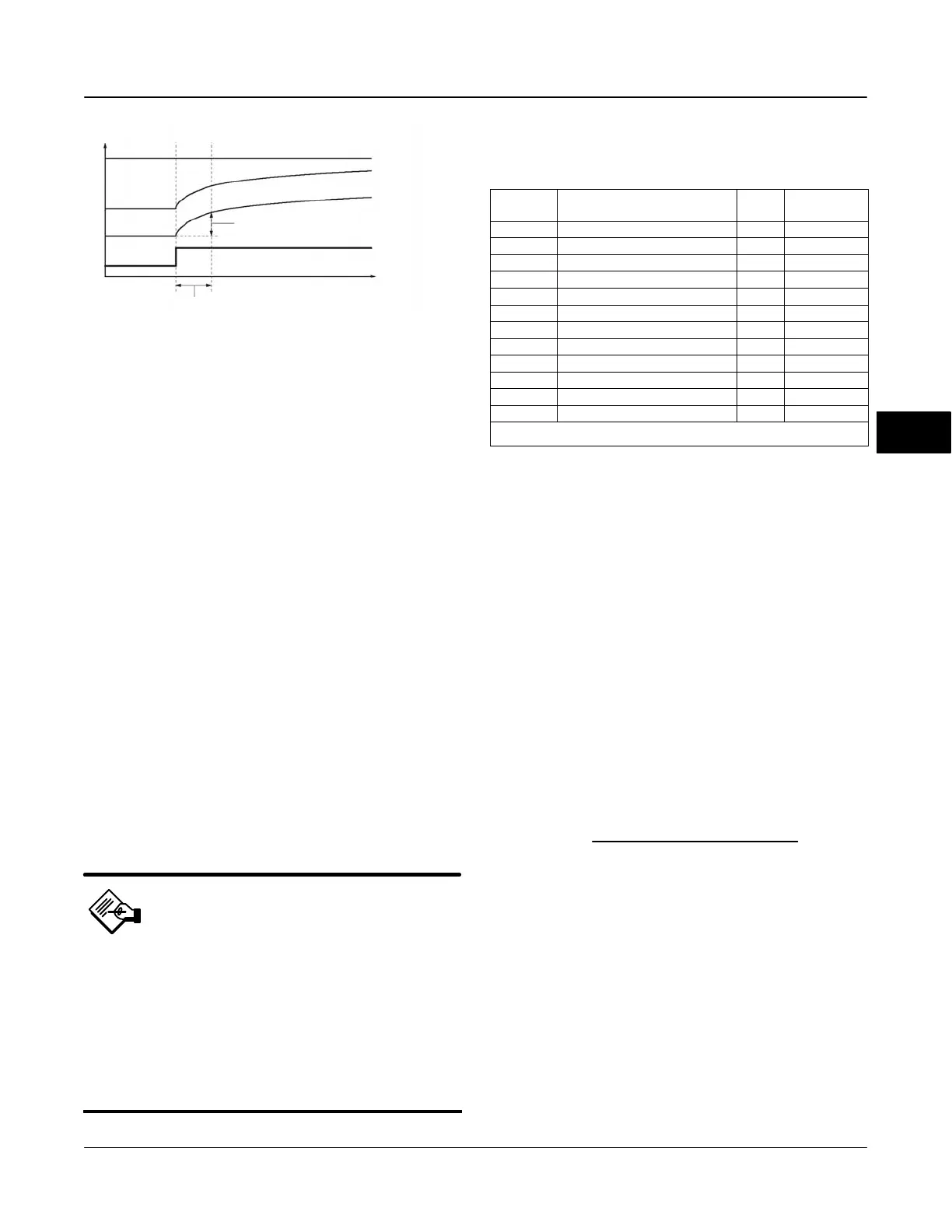
Figure 5-25. Analog Input Function Block Timing Diagram
OUT (mode in man)
OUT (mode in auto)
PV
63% of Change
TIME (seconds)
FIELD_VAL
PV_FTIME
FIELDBUS-FBUS_03A
Status Handling
The AI block only gets Good Non-Specified Unlimited
or Bad Device Failure for status from the transducer.
This is reflected in FIELD_VAL.STATUS [19.1].
PV.STATUS [7.1] is the same as
FIELD_VAL.STATUS [19.1]. OUT.STATUS [8.1] can
also reflect Bad, Out of Service in addition to
PV.STATUS [7.1] values.
In the STATUS_OPTS [14] parameter, you can select
from the following options to control the status
handling:
Propagate Fail Forward—If the status from the
sensor is Bad, Device failure or Bad, Sensor failure,
propogate it to OUT without generating an alarm. The
use of these sub-status in OUT is determined by this
option. Through this option, you may determine
whether alarming (sending out an alert) will be done by
the block or propagated downstream for alarming.
Uncertain if in Manual mode—The status of the
Output is set to Uncertain when the mode is set to
Manual.
Note
1. The instrument must be in Out of
Service mode to set the status option.
2. The AI block only supports the
Uncertain if in Manual and Propagate
failure. Unsupported options are not
grayed out; they appear on the screen
in the same manner as supported
options.
Channels
Table 5-53. Channel Selections for the Analog Input Function
Block
Channel Parameter
(1)
Block
Index
Number
2 TRAVEL_TARGET TB 49
3 FINAL_POSITION_VALUE TB 17
4 TRAVEL TB 34
5 SUPPLY_PRESS TB 35
6 PRESSURE_A TB 36
7 PRESSURE_B TB 37
8 PRESSURE_DIFF TB 38
9 DRIVE_SIGNAL TB 53
10 TRAVEL_DEVIATION TB 52
11 TEMPERATURE TB 48
12 CYCLE_COUNT TB 73
13 TRAVEL_ACCUMULATION TB 72
1. Refer to table 5-13 for transducer block parameter descriptions and table 5-24 for
AO parameter descriptions.
Filtering
The filtering feature changes the response time of the
device to smooth variations in output readings caused
by rapid changes in input. You can adjust the filter
time constant (in seconds) using the PV_FTIME [18]
parameter. Set the filter time constant to zero to
disable the filter feature.
Signal Conversion
You can set the signal conversion type with the
Linearization Type (L_TYPE [16]) parameter. You can
view the converted signal (in percent of XD_SCALE
[10]) through the FIELD_VAL [19] parameter.
100 X (Channel Value) − EU *@0%
FIELD_VAL =
(EU *@100% − EU *@0%)
*XD_SCALE values
You can choose from direct, indirect, or indirect
square root signal conversion with the L_TYPE [16]
parameter.
Direct
Direct signal conversion allows the signal to pass
through the accessed channel input value (or the
simulated value when simulation is enabled).
PV = Channel Value
5
 Loading...


