AO Function Block
March 2006
5-69
B2718-1 / IL
CAS_IN, 2
OUT
SP
Time
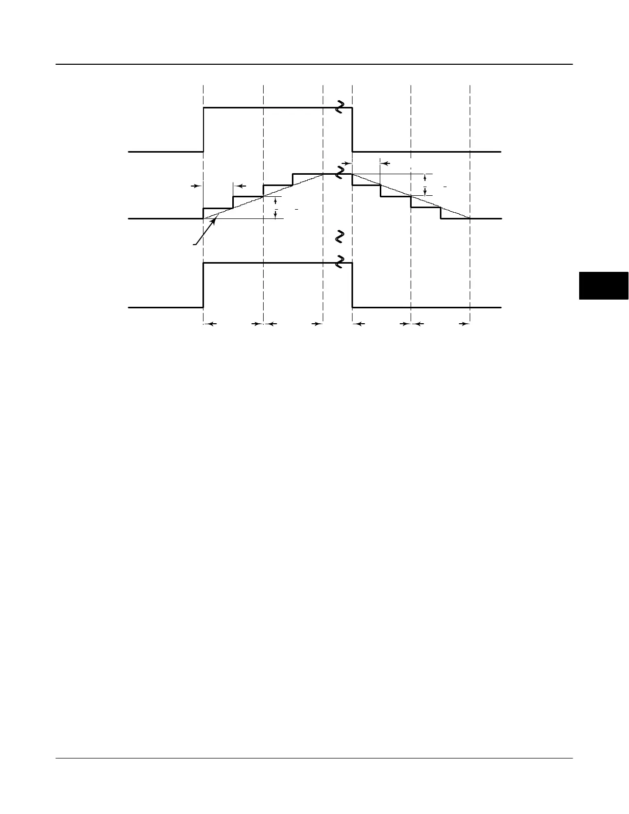
Figure 5-10. Analog Output Function Block Timing Diagram
SP RATE UP
SP
RATE DN
1 second 1 second 1 second 1 second
1 macrocycle
1 macrocycle
TRANSDUCER BLOCK
TRAVEL TARGET
options, the tracking options, and the conversion and
status calculations.
Output Block PV Status
The Output Block PV Status is determined by the
enabled status of the Resource Block parameter
FEATURE_SEL [18], the Transducer Block mode, and
enabled Active PlantWeb alarms. Refer to table 5-1.
Set Point Selection and Limiting
To select the source of the SP [8] value use the
MODE [5] attribute. In Automatic (Auto) mode, the
local, manually-entered SP [8] is used. In Cascade
(Cas) mode, the SP [8] comes from another block
through the CAS_IN [17] input connector. In
RemoteCascade (RCas) mode, the SP [8] comes from
a host computer that writes to RCAS_IN [28]. The
range and units of the SP [8] are defined by the
PV_SCALE [11] attribute.
In Manual (Man) mode the SP [8] automatically tracks
the PV [7] value when you select the SP-PV Track in
Man I/O option. The SP [8] value is set equal to the
PV value when the block is in manual mode, and is
enabled in IO_OPTS [14]. You can disable this option
in Man or OOS mode only.
The SP [8] value is limited to the range defined by the
setpoint high limit attribute (SP_HI_LIM [20]) and the
setpoint low limit attribute (SP_LO_LIM [21]).
In Auto mode, the rate at which a change in the SP [8]
is passed to OUT [9] is limited by the values of the
setpoint upward rate limit attribute (SP_RATE_UP
[19]) and the setpoint downward rate limit attribute
(SP_RATE_DN [18]). A limit of zero disables rate
limiting, even in Auto mode.
As shown in figure 5-10, the block executes a
percentage of the set point change each macrocycle.
For example, if the set point rate is set at 10% per
second and the macrocycle is 500 milliseconds (0.5
seconds or 50% of 1 second), then during the first
macrocycle the set point will change 5% (50% of the
10% per second rate). If the macrocycle is 750
milliseconds (0.75 seconds or 75% of 1 second), then
during the first macrocycle the setpoint will change
7.5% (75% of 10).
When the transducer block receives the setpoint
change from an AO block with rate limits, it will
smoothly move the valve to the requested setpoint at
the rate limit configured in the AO block.
In Auto mode, the converted SP [8] value is stored in
the OUT [9] attribute. In Man mode, the OUT [9]
attribute is set manually, and is used to set the analog
output defined by the CHANNEL [22] parameter.
You can access the actuator position associated with
the output channel through the READBACK [16]
parameter (in OUT units) and in the PV [7] attribute (in
5
 Loading...


