DVC6000f Series
March 2006
8-2
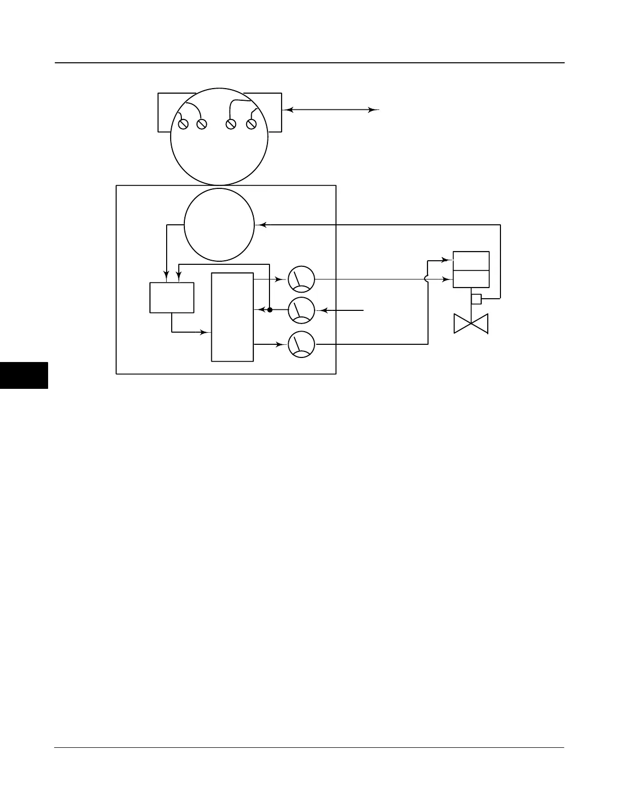
Figure 8-1. DVC6000f Series Digital Valve Controller Block Diagram
E0408-1 / IL
DIGITAL
SETPOINT
9–32 VOLT
FIELDBUS
SUPPLY
PRESSURE
PRINTED
WIRING BOARD
PNEUMATIC
RELAY
I/P
CONVERTER
OUTPUT A
OUTPUT B
VALVE TRAVEL
FEEDBACK
AUXILIARY
TERMINALS
TERMINAL BOX
DRIVE
SIGNAL
VALVE AND ACTUATOR
DIRECT ACTING RELAY TYPE A
ZERO POWER CONDITION = VALVE CLOSED
Digital Valve Controller Operation
DVC6000f Series digital valve controllers have a single
module base that may be easily replaced in the field
without disconnecting field wiring or tubing. The
master module contains the following submodules:
current-to-pneumatic (I/P) converter, printed wiring
board assembly, and pneumatic relay. The master
module can be rebuilt by replacing the submodules.
See figures 8-1 and 8-2.
DVC6000f Series digital valve controllers are
bus-powered instruments that provide a control valve
position in response to a digital setpoint from the
control room. The following describes a direct acting
Type DVC6010f digital valve controller mounted on a
sliding stem piston actuator, where the valve is closed
with zero power to the instrument.
The setpoint is routed into the terminal box through a
single pair of wires and then to the printed wiring
board assembly submodule where it is read by the
microprocessor, processed by a digital algorithm, and
converted into an analog I/P drive signal.
As the setpoint increases, the drive signal to the I/P
converter increases, increasing the I/P output
pressure. The I/P output pressure is routed to the
pneumatic relay submodule. The relay is also
connected to supply pressure and amplifies the small
pneumatic signal from the I/P converter. The relay
accepts the amplified pneumatic signal and provides
two output pressures. With Relay Type A, an
increasing setpoint will produce increasing pressure at
output A and decreasing pressure at output B (with
Relay Type B only output A is available and is
reversed). The output A pressure is used for
double-acting and single-acting direct applications.
The output B pressure is used for double-acting and
single-acting reverse applications.
8
 Loading...


