DVC6000f Series
March 2006
10-6
CAUTION
Exercise care when performing
maintenance on the module base.
Reinstall the cover to protect the I/P
converter and gauges when servicing
other submodules.
In order to maintain accuracy
specifications, do not strike or drop
the I/P converter during submodule
maintenance.
I/P Converter
WARNING
Refer to the Maintenance WARNING at
the beginning of this section.
Refer to figures 11-1 through 11-8 for key number
locations. The I/P converter (key 41) is located on the
front of the module base.
Note
After I/P converter submodule
replacement, calibrate the digital valve
controller to maintain accuracy
specifications.
Replacing the I/P Filter
A screen in the supply port beneath the I/P converter
serves as a secondary filter for the supply medium. To
replace this filter, perform the following procedure:
1. Remove the I/P converter (key 41) and shroud (key
169) as described in the Removing the I/P Converter
procedure.
2. Remove the screen (key 231) from the supply port.
3. Install a new screen in the supply port as shown in
figure 10-3.
4. Inspect the O-ring (key 39) in the I/P output port. if
necessary, replace it.
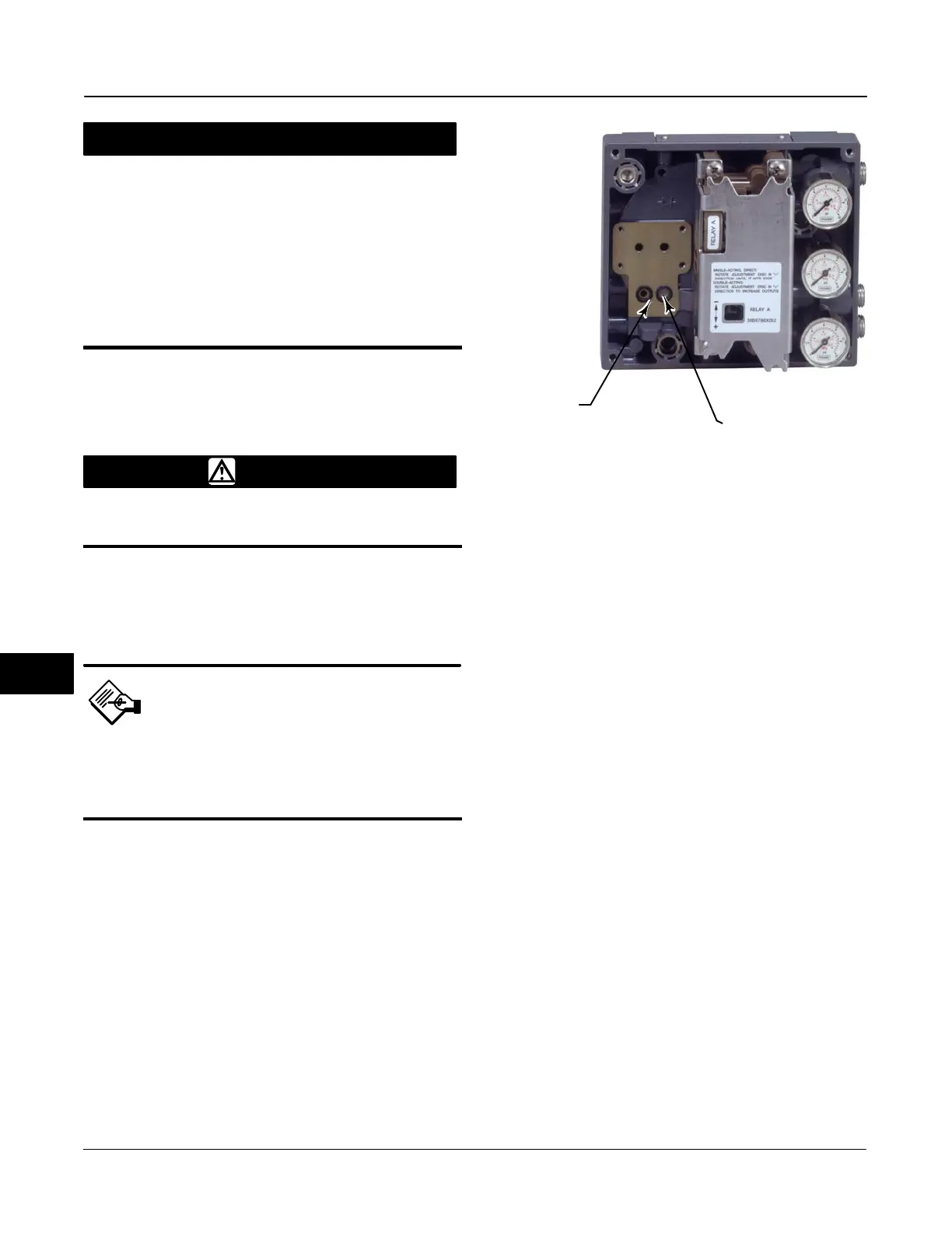
Figure 10-3. I/P Filter Location
O-RING LOCATED
IN I/P CONVERTER
OUTPUT PORT
W8072
SCREEN (FILTER) LOCATED
IN I/P CONVERTER
SUPPLY PORT
5. Reinstall the I/P converter (key 41) and shroud (key
169) as described in the Replacing the I/P Converter
procedure.
Removing the I/P Converter
1. Remove the front cover (key 43), if not already
removed.
2. Refer to figure 10-4. Using a 2.5 mm hex socket
wrench, remove the four socket-head screws (key 23)
that attach the shroud (key 169) and I/P converter
(key 41) to the module base (key 2).
3. Remove the shroud (key 169); then pull the I/P
converter (key 41) straight out of the module base
(key 2). Be careful not to damage the two electrical
leads that come out of the base of the I/P converter.
4. Ensure that the O-ring (key 39) and screen (key
231) stay in the module base and do not come out
with the I/P converter (key 41).
Replacing the I/P Converter
1. Refer to figure 10-3. Inspect the condition of the
O-ring (key 39) and screen (key 231) in the module
base (key 2). Replace them, if necessary. Apply
silicone lubricant to the O-rings.
2. Ensure the two boots (key 210) shown in figure
10-4 are properly installed on the electrical leads.
3. Install the I/P converter (key 41) straight into the
module base (key 2), taking care that the two electrical
leads feed into the guides in the module base. These
guides route the leads to the printed wiring board
assembly submodule.
10
 Loading...


