EasyManuals Logo

Emerson Micro Motion Installation Manual

Emerson Micro Motion
74 pages
To Next Page IconTo Next Page
To Previous Page IconTo Previous Page
Page #38 background imageLoading...
Page #38 background image
34 Micro Motion
®
Model D and DT Sensors Instruction Manual
Wiring continued
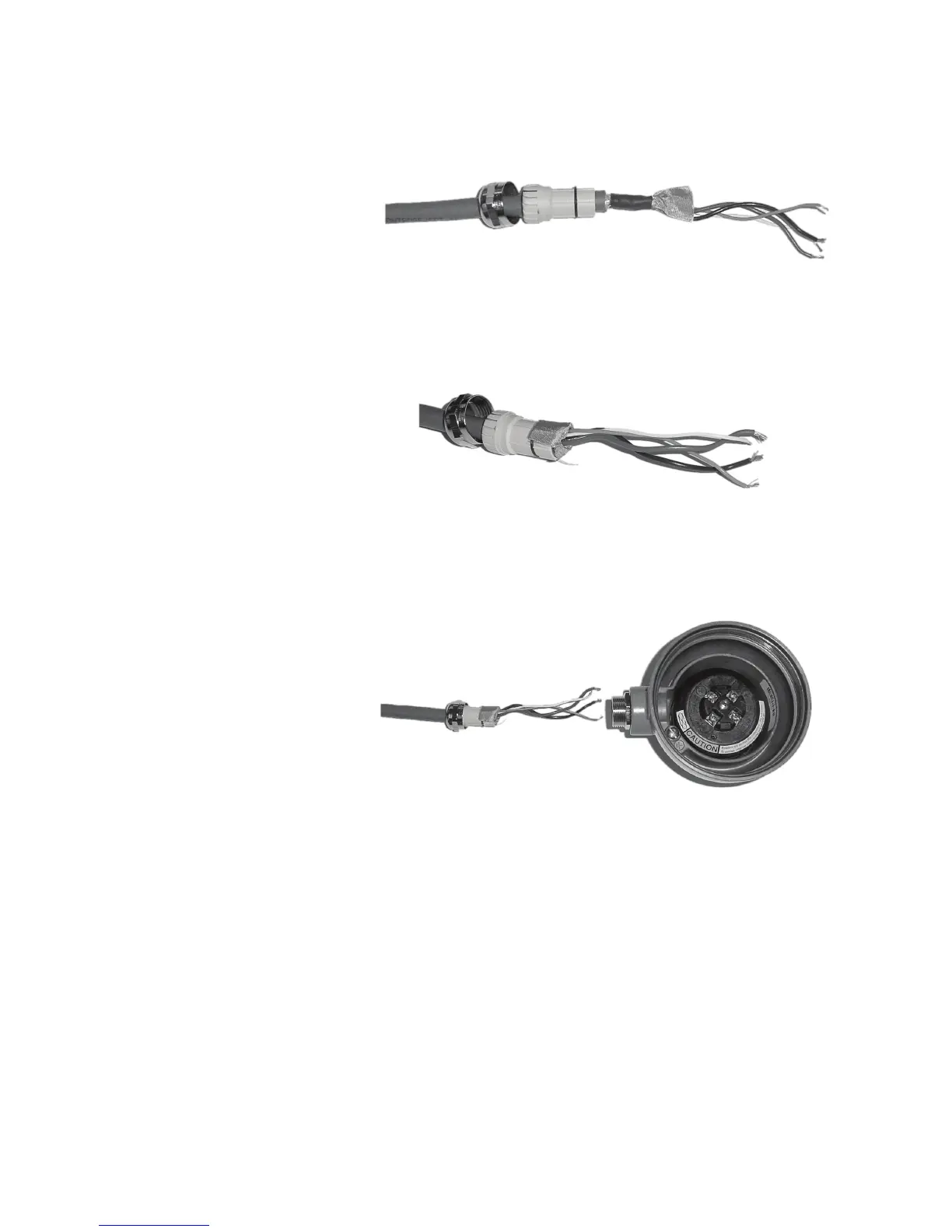
g. Position gland clamping insert so the interior end is flush with the
heat shrink.
h. Fold the cloth shield or braid and drain wires over the clamping
insert and approximately 1/8 inch (3 mm) past the O-ring.
i. Install the gland body into the core processor housing conduit
opening.
5. Insert the wires through the gland body and assemble the gland by
tightening the gland nut.
6. Identify the wires in the 4-wire cable. The 4-wire cable supplied by
Micro Motion consists of one pair of 18 AWG (0,75 mm
2
) wires (red
and black), which should be used for the VDC connection, and one
pair of 22 AWG (0,35 mm
2
) wire (green and white), which should be
used for the RS-485 connection. Connect the four wires to the
numbered slots on the core processor, matching corresponding
numbered terminals on the transmitter.

Other manuals for Emerson Micro Motion

Questions and Answers:

Question and Answer IconNeed help?

Do you have a question about the Emerson Micro Motion and is the answer not in the manual?

Emerson Micro Motion Specifications

General IconGeneral
CategoryMeasuring Instruments
ManufacturerEmerson
BrandMicro Motion
TypeCoriolis Flow Meter
Output4-20 mA, HART, Foundation Fieldbus, Profibus, Modbus
Power Supply24 V DC
MaterialStainless Steel, Hastelloy
Process ConnectionFlanged, Threaded
CertificationsATEX, IECEx, CSA, SIL
Pressure RatingVaries by model; up to 10, 000 psi (690 bar)
Temperature RangeVaries by model; -400 to 750°F (-240 to 400°C)

Related product manuals