Micro Motion
®
Model D and DT Sensors Instruction Manual 51
Troubleshooting continued
• Use the host controller
If necessary, test the process fluid to confirm the flowmeter
measurement is correct.
Checking for RF or transient-voltage interference
Radio-frequency (RF) or transient-voltage interference can affect the
input or output signals at the transmitter. If you suspect interference, and
can eliminate the source, do so before checking the alternatives
described below.
Output wiring. Output wiring can be affected by interference. Make
sure output wiring from the transmitter is properly grounded in
accordance with the instructions in the transmitter manual. Also make
sure no wires remain exposed at either end of output wiring.
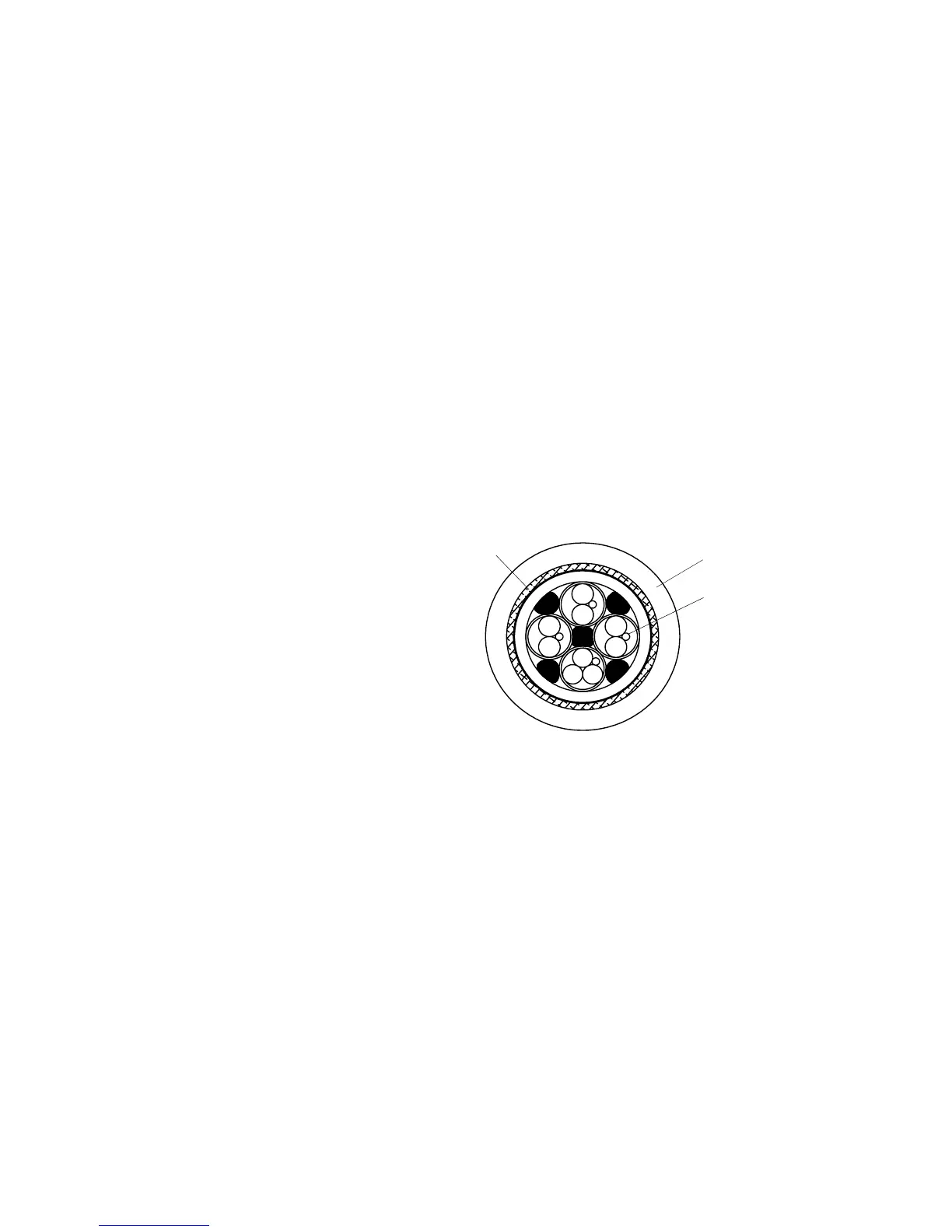
Flowmeter cable. If the flowmeter cable does not have an external
shield (see illustration, below), and is not installed in conduit, it could be
affected by interference. Also make sure no wires remain exposed at
either end of the flowmeter cable.
Cross-section of externally shielded cable
Troubleshooting at the sensor
The tables in the preceding sections refer you to this section for
instructions on troubleshooting at the sensor. To troubleshoot at the
sensor, you might need a digital multimeter (DMM) or similar device. For
some procedures, you might also need the transmitter manual.
Checking flowmeter grounding
The sensor can be grounded via the piping, as long as joints in the
pipeline are ground-bonded, or by means of a ground screw on the
sensor case. See illustration, below. Transmitter grounding is described
in the transmitter instruction manual.
If the sensor is not grounded via the piping, and if national standards are
not in effect, adhere to these guidelines to ground the sensor via the
junction box:
• Use copper wire, 14 AWG (2,5 mm
2
) or larger wire size for grounding.
• Keep all ground leads as short as possible, less than 1 ohm
impedance.
• Connect ground leads directly to earth, or follow plant standards.